
Safe mailbox device

A letterbox and safety technology, applied in printing, typewriters, etc., can solve the problems of reducing letterbox coding operations, failing to meet the needs of use, and fixing devices that cannot meet various letterboxes with different diameters, etc., to achieve the effect of convenient handling

Inactive Publication Date: 2018-07-03
QUZHOU YANHANG MACHINERY TECH CO LTD
View PDF0 Cites 0 Cited by
  • Summary
  • Abstract
  • Description
  • Claims
  • Application Information

AI Technical Summary

Problems solved by technology

[0002] The letterbox is an important carrier for the post office to receive mail. Before the letterbox is put into use, the surface of the letterbox will be marked with a code to better count and identify the letterboxes. Most of the existing letterboxes are cylindrical, and the cylindrical letterbox It also includes a variety of letter boxes with different diameters. When spraying the letter boxes, it is usually necessary to fix the letter boxes in order to better complete the inkjet operation. However, the existing fixing devices can no longer meet the needs of fixing various letter boxes with different diameters. But only the letterboxes of the same diameter can be fixed, which reduces the coding work of the letterboxes. Therefore, the existing fixing devices can no longer meet the existing use requirements.

Method used


Image

  • Safe mailbox device
  • Safe mailbox device
  • Safe mailbox device

Examples


Embodiment Construction

[0020] The preferred embodiments of the present invention will be described in detail below in conjunction with the accompanying drawings, so that the advantages and features of the present invention can be more easily understood by those skilled in the art, so as to define the protection scope of the present invention more clearly.

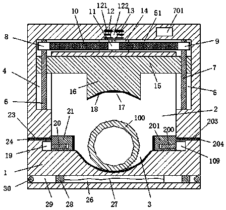
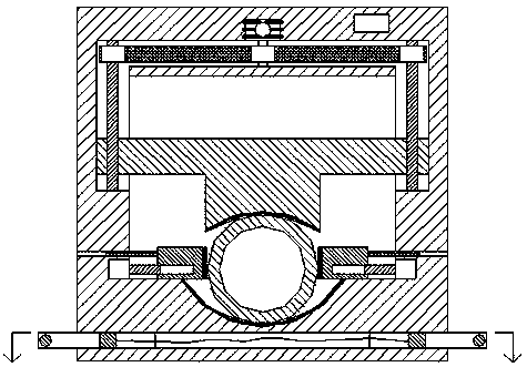
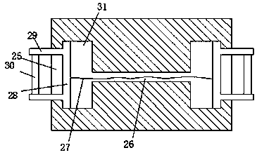
[0021] refer to Figure 1-4 The safe mailbox device shown includes a base 1 and a container 2 arranged in the base 1 and penetrated front and rear. The middle end of the bottom side wall of the container 2 is provided with a first arc groove 3 , the top of the left side wall of the storage bin 2 and the top of the right side wall are respectively provided with a left sliding groove 4 and a right sliding groove 5, and the top side wall of the storage bin 2 is provided with a The groove 4 and the right sliding groove 5 are connected to the groove 51. The base plate 15 that can slide up and down is arranged in the storage bin 2, and the middle end o...


PUM


Abstract

The invention discloses a safe mailbox device. The safe mailbox device comprises a base and an accommodating bin, wherein the accommodating bin is arranged in the base and penetrates through front andback. A first arc-opening groove is arranged in the middle end of the bottom side wall of the accommodating bin. A left sliding-moving groove and a right sliding-moving groove are oppositely and correspondingly arranged on the top of the left side wall of the accommodating bin and the upper part of top of the right side wall of the accommodating bin. A through groove is formed in the top side wall of the accommodating bin, and the through groove is connected with the left sliding-moving groove and the right sliding-moving groove. A base plate capable of sliding and moving up and down is arranged in the accommodating bin. A protruding lower block is arranged at the middle end of the bottom part of the base plate, and a second arc-opening groove is arranged in the bottom part of the protruding lower block. According to the safe mailbox device, the structure is reasonable, operation is simple, carrying is convenient, clamping of the mailbox is safe and stable, skewing of the mailbox doesnot occur, following code-spraying operation is conveniently achieved, mailbox with different sizes can be clamped at the same time, clamping fixing cost of the mailbox is significantly reduced, andthe convenient mailbox device is suitable for popularization and usage.

Description

technical field [0001] The invention relates to the technical field of mailboxes, in particular to a safe mailbox device. Background technique [0002] The mailbox is an important carrier for the post office to receive mail. Before the mailbox is put into use, the surface of the mailbox will be marked with a code, so as to better count and identify the mailboxes. The existing mailboxes are mostly cylindrical, and the cylindrical mailbox It also includes a variety of letterboxes with different diameters. When printing on letterboxes, it is usually necessary to fix the letterboxes in order to better complete the inkjet operation. And can only fix the letter box of same diameter, this has just reduced the inkjet operation of letter box, therefore, existing fixture can't satisfy existing use requirement. Contents of the invention [0003] The technical problem to be solved by the present invention is to provide a safe mailbox device, which can solve the above-mentioned proble...

Claims


Application Information

Patent Timeline
Patent Type & Authority Applications(China)
IPC IPC(8): B41J3/407
CPCB41J3/4073
Inventor 叶利萍
Owner QUZHOU YANHANG MACHINERY TECH CO LTD
Learn More