
A rear positioning device for a numerically controlled lathe

A CNC lathe and post-positioning technology, which is used in positioning devices, manufacturing tools, metal processing machinery parts, etc., can solve the problems of time-consuming disassembly and assembly of positioning rods, injuries to workers, and reduced processing efficiency.

Active Publication Date: 2021-09-14
费斯托气动有限公司
View PDF5 Cites 0 Cited by
  • Summary
  • Abstract
  • Description
  • Claims
  • Application Information

AI Technical Summary

Problems solved by technology

[0003] In the prior art, the method of rear positioning is: when installing the workpiece for the first time, the worker finds the proper position of the workpiece, fastens the workpiece through the chuck, and then fixes the workpiece at the rear of the workpiece. A positioning rod is installed to facilitate the rapid positioning of the subsequent processed parts; the positioning rod is usually locked in the radial direction by a nut, so every time the workpiece needs to be changed, the disassembly and assembly of the positioning rod is very time-consuming and greatly The processing efficiency is reduced, and at the same time, workers still have the risk of injuring their hands, and work-related accidents occur frequently

Method used


Image

  • A rear positioning device for a numerically controlled lathe
  • A rear positioning device for a numerically controlled lathe
  • A rear positioning device for a numerically controlled lathe

Examples


Embodiment Construction

[0039] The present disclosure will be further described below in conjunction with the accompanying drawings and embodiments.

[0040] It should be pointed out that the following detailed description is exemplary and intended to provide further explanation to the present application. Unless defined otherwise, all technical and scientific terms used herein have the same meaning as commonly understood by one of ordinary skill in the art to which this application belongs.

[0041] It should be noted that the terminology used here is only for describing specific implementations, and is not intended to limit the exemplary implementations according to the present application. As used herein, unless the context clearly dictates otherwise, the singular is intended to include the plural, and it should also be understood that when the terms "comprising" and / or "comprising" are used in this specification, they mean There are features, steps, operations, means, components and / or combinati...


PUM


Abstract

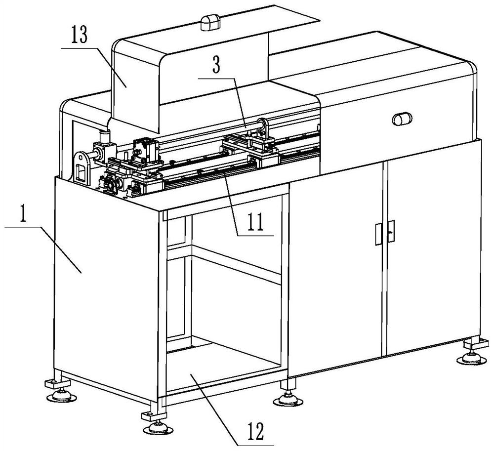
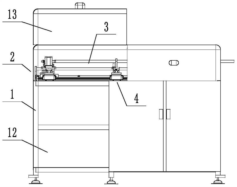
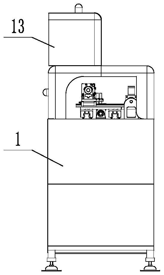
The invention discloses a rear positioning device of a numerically controlled lathe, which comprises a frame, which is arranged on the rear side of the numerically controlled lathe, and further comprises a positioning rod, a propulsion part used to drive the positioning rod to move forward and backward, and used to support the positioning rod. The supporting part of the rod or workpiece and the locking part for locking the position of the advancing part in the axial direction; the positioning rod is connected with the advancing part at one end, and the other end is used for axially locking the advancing part. The workpiece is limited; the positioning rod can be adjusted in the front and rear directions according to the workpieces of different lengths, which is convenient for positioning the workpieces of different lengths, saves the time of changing models, improves the efficiency of changing models, thereby improving production efficiency and reducing work injuries Accidents happen.

Description

technical field [0001] The invention relates to the technical field of machining positioning, in particular to a rear positioning device for a numerically controlled lathe. Background technique [0002] In recent years, with the gradual advancement of Industry 4.0 and the rapid development of automated production lines, how to further improve production efficiency is a major problem faced by various enterprises; in the field of machining, when workpieces are processed by CNC lathes, it is necessary to The workpiece is post-positioned. [0003] In the prior art, the method of rear positioning is: when installing the workpiece for the first time, the worker finds the proper position of the workpiece, fastens the workpiece through the chuck, and then fixes the workpiece at the rear of the workpiece. A positioning rod is installed to facilitate the rapid positioning of the subsequent processed parts; the positioning rod is usually locked in the radial direction by a nut, so eve...

Claims


Application Information

Patent Timeline
Patent Type & Authority Patents(China)
IPC IPC(8): B23Q3/18
CPCB23Q3/18
Inventor 马凡营王健亭王景辉聂红军孟凡飞王刚李帅张鹏
Owner 费斯托气动有限公司
Learn More