
Floating wind turbine generator installation

a technology of wind turbine generator and floating foundation, which is applied in the direction of machines/engines, vessels, transportation and packaging, etc., can solve the problems of increasing safety risks, damage to the interface between the floating foundation and the wind turbine generator, and the interface between, so as to increase the buoyancy of the floating foundation

Active Publication Date: 2021-11-18
VESTAS WIND SYST AS
View PDF0 Cites 1 Cited by
  • Summary
  • Abstract
  • Description
  • Claims
  • Application Information

AI Technical Summary

Benefits of technology

The invention is a method of installing a wind turbine generator onto a floating platform. The method involves pre-ballasting the platform, bringing the wind turbine generator component close to the platform, and then removing ballast from the platform to increase its buoyancy. This increases the weight of the wind turbine generator component supported by the platform from almost zero to its full weight. This method reduces risks associated with movement of the platform during installation and ensures stability of the wind turbine generator component. The method may also involve securing the wind turbine generator component to the platform to prevent displacement.

Problems solved by technology

Movement of the floating foundation in this way may lead to increased safety risks associated with the installation as changing in vertical position of the foundation may lead to angled lifting with a tension line not being vertical and hence submitting the lifting equipment to forces off the intended axis.
Furthermore, it may cause damage to the interface between the floating foundation and the wind turbine generator or the interface between components of the wind turbine generator during the installation.

Method used


Image

  • Floating wind turbine generator installation
  • Floating wind turbine generator installation
  • Floating wind turbine generator installation

Examples


Embodiment Construction

)

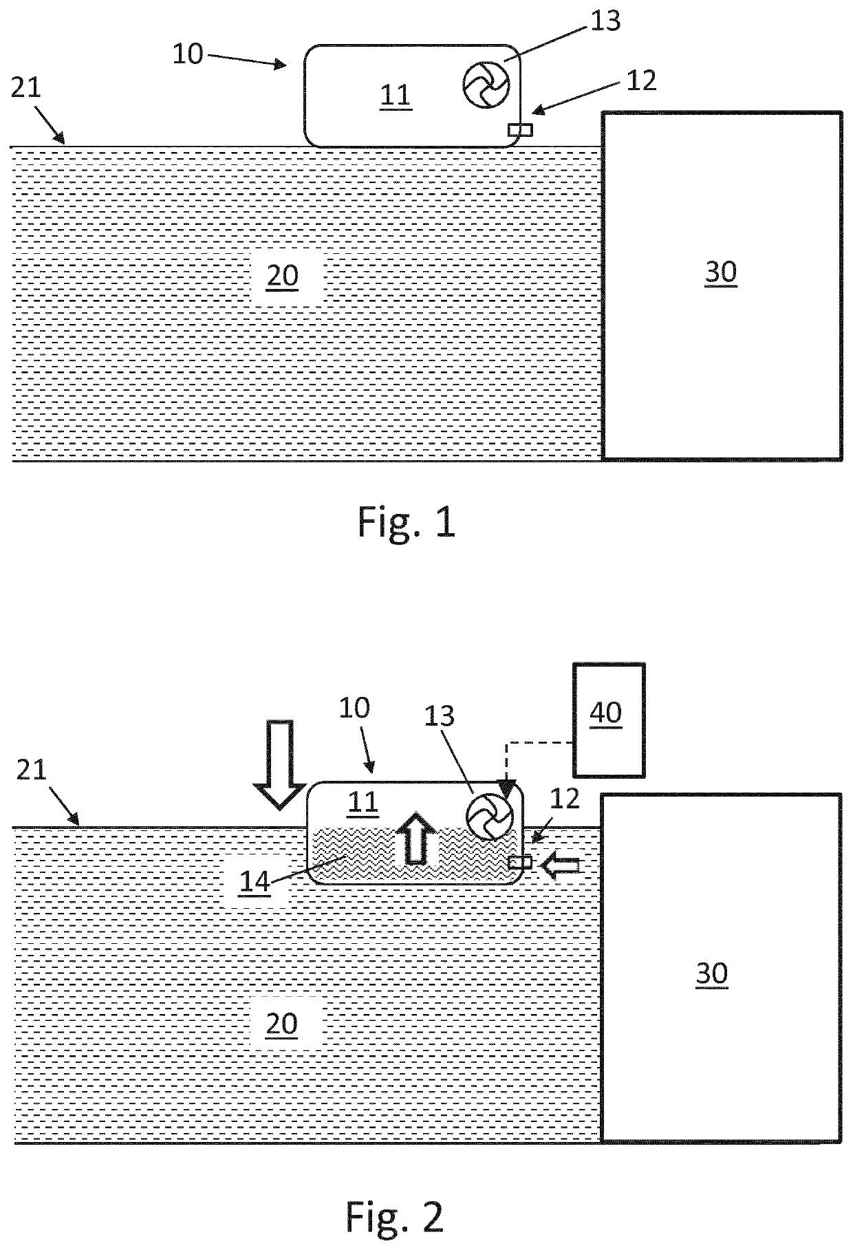
[0041]FIG. 1 shows a floating foundation 10 floating on the surface 21 of a body of water 20 adjacent a quayside 30.

[0042]The floating foundation 10 has an internal volume 11 for containing a quantity of ballast. In an example the ballast is water ballast. The internal volume 11 of the floating foundation 10 is in selective fluid communication with the body of water 20 via a port 12 of the floating foundation 10. A pump 13 is arranged to pump water ballast either out from the internal volume 11 through the port 12, or through the port 12 into the internal volume 11. In doing so, the quantity of water ballast in the internal volume 11 is variable such that the floating foundation 10 has variable buoyancy.

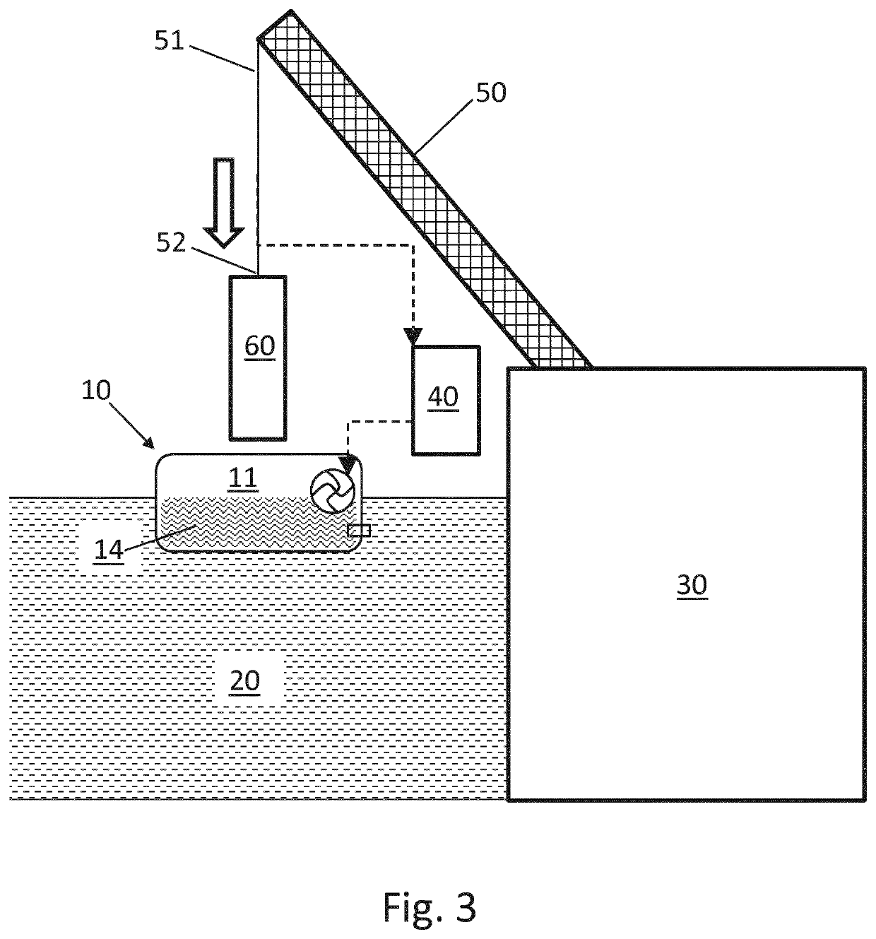
[0043]As shown in FIG. 2, a controller 40 is coupled with the pump 13. Under the action of the controller 40 the pump 13 is filling the internal volume 11 of the floating foundation 10 with water ballast 14 by drawing water from the body of water 20 in through the port 12 such that ...


PUM


Abstract

A method of installing a wind turbine generator onto a floating foundation. The floating foundation has variable buoyancy and is pre-ballasted to float at a predetermined vertical position before installation of a wind turbine generator component onto the floating foundation. A wind turbine generator component supported by lifting equipment is brought towards the floating foundation until contact is made with the floating foundation. Ballast is removed from the floating foundation to increase the buoyancy of the floating foundation such that weight of the wind turbine generator component supported by the floating foundation is increased from substantially zero to substantially the entire weight of the wind turbine generator component. The vertical position of the floating foundation is substantially unchanged during transferring weight of the wind turbine generator component onto the floating foundation.

Description

FIELD OF THE INVENTION[0001]The present invention relates to a system and method of installing a wind turbine generator onto a floating foundation.BACKGROUND OF THE INVENTION[0002]Offshore wind turbine generators for example for deeper water operation can be mounted to a floating foundation. The floating foundation has buoyancy to support the weight of the wind turbine generator mounted upon it. Various types of floating foundation are known which are coupled to the seabed and stabilised in different ways.[0003]One such floating foundation is a buoyancy stabilised floating foundation of a semi-submersible type. The floating foundation typically has a plurality of stabilising columns including internal volumes for containing water ballast for smaller adjustments of tilt of the foundation. The water ballast may be introduced or removed from the body of water in which the floating foundation is floating. The level, or vertical depth, as well as the tilt attitude of the floating foundat...

Claims


Application Information

Patent Timeline
IPC IPC(8): F03D13/25F03D13/10B63B35/44B63B75/00B63B1/10
CPCF03D13/25F03D13/10B63B35/44F05B2240/93B63B1/107B63B2035/446B63B75/00Y02E10/727Y02E10/72B63B77/10B63B39/03
Inventor OLSEN, ALF
Owner VESTAS WIND SYST AS
Learn More