An automatic corner protector wrapping machine

A corner protection and machine closing technology, applied in the directions of packaging, transportation and packaging, and the type of packaging items, can solve the problems of low efficiency and high labor intensity, and achieve the effect of liberating labor and improving the degree of full automation

Active Publication Date: 2020-03-17
苏州德睿联自动化科技有限公司
View PDF6 Cites 0 Cited by
  • Summary
  • Abstract
  • Description
  • Claims
  • Application Information

AI Technical Summary

Problems solved by technology

There is no mechanical equipment for this kind of corner wrapping in the existing market. Due to cost considerations, traditional manual packing of corners is used, which is labor-intensive, low in efficiency, and labor also requires management costs, so A purely automated mechanical packaging corner equipment is a subject to be developed urgently

Method used


Image

  • An automatic corner protector wrapping machine
  • An automatic corner protector wrapping machine
  • An automatic corner protector wrapping machine

Examples


Embodiment Construction

[0023] The present invention will be described in detail below with regard to specific accompanying drawings.

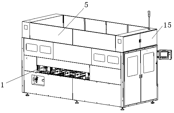
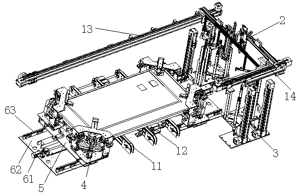
[0024] Such as figure 1 and figure 2 An automatic corner wrapping machine is shown, including a frame 1, an assembly line 11 arranged on the frame 1 for automatic product delivery, and a correcting mechanism 12 for positioning the product, which is set above the frame 1 There are two X1 shafts 13 and X2 shafts 14 of the same height. On the X1 shafts 13 and X2 shafts 14, a stepping motor 61 drives a feeding mechanism, and a bin storage mechanism 3 is arranged below the feeding mechanism. , the two sides of the assembly line 11 are provided with a cladding mechanism 4, wherein:

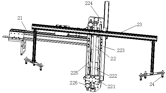
[0025] Such as image 3 As shown, the feeding mechanism is composed of a beam 21, a lifting cylinder 22 arranged on the beam 21, and a suction cup assembly driven by the lifting cylinder 22;

[0026] Such as Figure 4 As shown, the bin storage mechanism 3 has four groups, and each group ...


PUM


Abstract

The invention relates to an automatic angle bead wrapping machine which comprises a rack, an assembly line which is arranged on the rack and used for automatically conveying products, and a restoration mechanism which is used for locating the products. The automatic angle bead wrapping machine is characterized in that an X1 shaft and an X2 shaft at equivalent heights are arranged above the rack; aloading mechanism is driven on the X1 shaft and the X2 shaft by a stepping motor; stock bin storage mechanisms are arranged below the loading mechanism; wrapping mechanisms are arranged on the two sides of the assembly line; each wrapping mechanism consists of a bottom plate, and a bracket and an air cylinder group which are arranged on the bottom plate; and each air cylinder group comprises a jacking air cylinder, a right angle bending air cylinder, horizontal edge back air cylinders, horizontal edge pushing air cylinders, a vertical air cylinder and an inner angle extrusion air cylinder. According to the technical scheme, by employing the air cylinder groups to drive pushing plates connected with the heads of the various air cylinders to move in the specified directions, and through electrical setting on positions and sequential work of the air cylinder groups, the purpose of automatically wrapping the four corners of an assembly by a packing paper board is achieved, full automaticoperation is achieved, work force is liberated, and the full automation degree of a workshop is improved.

Description

technical field [0001] The invention relates to an automatic corner protection wrapping machine. Background technique [0002] The last link in the production of photovoltaic cells is to package the laid-up cell components. Since the four corners of the cell components are at right angles, it is necessary to wrap the four corners with cardboard to achieve transportation The problem of anti-collision wear during the process. There is no mechanical equipment for this kind of corner wrapping in the existing market. Due to cost considerations, traditional manual packing of corners is used, which is labor-intensive, low in efficiency, and labor also requires management costs, so A device for purely automated mechanical packaging of corners is a subject to be developed urgently. Contents of the invention [0003] The technical problem solved by the present invention is to provide an automatic corner protection wrapping machine that solves the above existing problems, realizes ...

Claims


Application Information

Patent Timeline
Patent Type & Authority Patents(China)
IPC IPC(8): B65B61/20B65B23/20
CPCB65B23/20B65B61/20
Inventor 雷水德高宜江胡刚沈青化曾庆礼
Owner 苏州德睿联自动化科技有限公司
Why Eureka
Try Eureka