Crane with dual-drive structure

A crane and dual-drive technology, applied in cranes and other directions, can solve the problems of increased maintenance costs, poor stability, and easy overload bending or damage of the support mechanism, so as to reduce maintenance costs and improve stability.

Inactive Publication Date: 2018-07-03
唐志赏
View PDF1 Cites 7 Cited by
  • Summary
  • Abstract
  • Description
  • Claims
  • Application Information

AI Technical Summary

Problems solved by technology

[0003] Patent No. 201420371367.X discloses a crane utility model patent, and it includes a crane body and a drill device detachably mounted on the crane body, driven by the crane body and performing pit digging operations. The crane provided by the utility model can install the drill bit device on its boom when the digging operation is required, and the drill bit device is driven by the boom and the hydraulic system to carry out the digging operation, so that the existing crane not only has the ability to lift heavy objects It also has the function of digging pits in the garden, thus expanding the operating field of the crane. However, in actual use, its support mechanism is supported by oil cylinders, which has high maintenance costs and poor stability, and its support mechanism There is no buffer mechanism in the crane. In actual use, the support mechanism is easily bent or damaged due to overload, which increases the maintenance cost in the later period. Therefore, we urgently need a crane that is easy to use, high in stability and has a dual-drive structure to solve the above problems.

Method used


Image

  • Crane with dual-drive structure
  • Crane with dual-drive structure
  • Crane with dual-drive structure

Examples


Embodiment Construction

[0023] The following will clearly and completely describe the technical solutions in the embodiments of the present invention with reference to the accompanying drawings in the embodiments of the present invention. Obviously, the described embodiments are only some, not all, embodiments of the present invention.

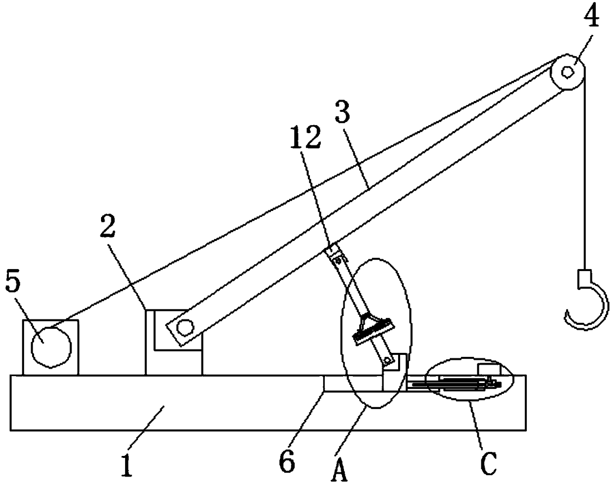
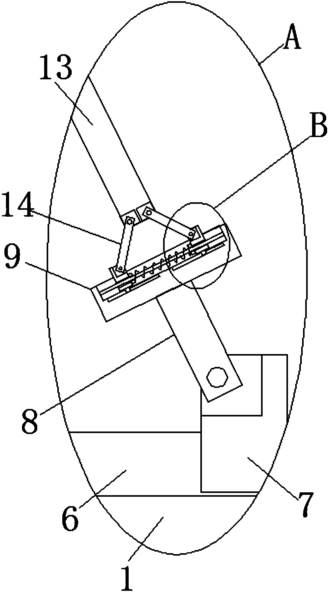
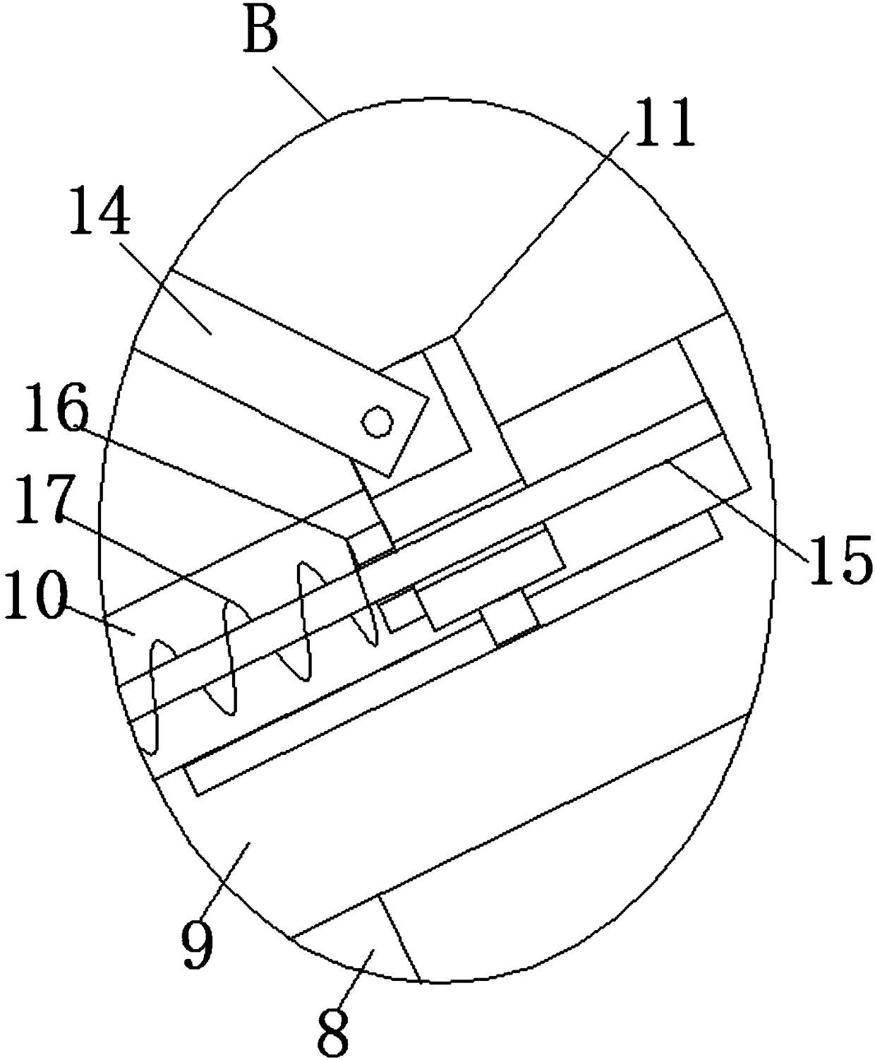
[0024] refer to Figure 1-5, a crane with a double-drive structure, including a base 1, a first fixed seat 2 is fixedly installed on the top of the base 1, and a boom 3 is rotatably installed on the top of the first fixed seat 2, and the boom 3 is far away from the first fixed seat. One end of the seat 2 is rotatably equipped with a pulley 4, one side of the first fixed seat 2 is provided with a winch 5 fixedly installed on the top of the base 1, and the top of the base 1 is provided with a first chute 6, which is slidably installed in the first chute 6. There is a first slider 7 located on the side of the first fixed seat 2 away from the winch 5, the top of the firs...


PUM


Abstract

The invention discloses a crane with a dual-drive structure. The crane with the dual-drive structure comprises a base. A first fixed base is fixedly installed on the top of the base. A crane boom is rotationally installed on the top of the first fixed base. A pulley is rotationally installed at the end, away from the first fixed base, of the crane boom. A winch fixedly installed on the top of thebase is arranged on one side of the first fixed base. A first sliding groove is formed in the top of the base. A first sliding block located on the side, away from the winch, of the first fixed base is installed in the first sliding groove in a sliding manner. The top of the first sliding block extends out of the first sliding groove and is rotationally provided with a first connecting rod. The first connecting rod is arranged in an inclined manner. A buffer base is fixedly installed at the end, away from the first sliding block, of the first connecting rod. According to the crane with the dual-drive structure, because dual-drive hoisting can be realized with the winch and a motor, the stability of hoisted articles can be improved, the first connecting rod, a second connecting rod and a third connecting rod are prevented from bending, and the later maintenance cost is reduced.

Description

technical field [0001] The invention relates to the technical field of cranes, in particular to a crane with a double-drive structure. Background technique [0002] A crane refers to a multi-action hoisting machine that vertically lifts and horizontally transports heavy objects within a certain range, also known as a crane, aerial crane, and crane. [0003] Patent No. 201420371367.X discloses a crane utility model patent, and it includes a crane body and a drill device detachably mounted on the crane body, driven by the crane body and performing pit digging operations. The crane provided by the utility model can install the drill bit device on its boom when the digging operation is required, and the drill bit device is driven by the boom and the hydraulic system to carry out the digging operation, so that the existing crane not only has the ability to lift heavy objects It also has the function of digging pits in the garden, thus expanding the operating field of the crane. ...

Claims


Application Information

Patent Timeline
Patent Type & Authority Applications(China)
IPC IPC(8): B66C23/06B66C23/68B66C23/62
CPCB66C23/06B66C23/62B66C23/68
Inventor 关宇航徐建豪唐志赏
Owner 唐志赏
Why Eureka
Try Eureka