
Stamping device with size detection function for case side plate machining

A size detection and stamping device technology, which is applied in the direction of forming tools, feeding devices, positioning devices, etc., can solve the problems of large equipment usage, wrong size, springback of metal sheets, etc.

Inactive Publication Date: 2021-08-17
源野网络科技(深圳)有限公司
View PDF0 Cites 3 Cited by
  • Summary
  • Abstract
  • Description
  • Claims
  • Application Information

AI Technical Summary

Problems solved by technology

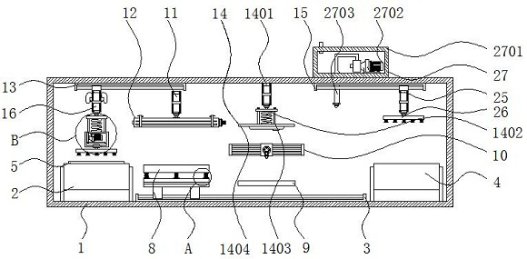
[0004] The purpose of the present invention is to provide a stamping device with a size detection function for processing the side plate of the chassis, so as to solve the problem that most of the existing stamping devices proposed in the above background technology directly place the metal sheet to the designated position, and then directly carry out the process by pressing the plate. Stamping, which causes the equipment to use greater pressure for stamping, and at the same time, the stamped metal sheet may rebound to a certain extent, resulting in the problem that the equipment punches the wrong size of the product

Method used


Image

  • Stamping device with size detection function for case side plate machining
  • Stamping device with size detection function for case side plate machining
  • Stamping device with size detection function for case side plate machining

Examples


Embodiment Construction

[0028] The following will clearly and completely describe the technical solutions in the embodiments of the present invention with reference to the accompanying drawings in the embodiments of the present invention. Obviously, the described embodiments are only some, not all, embodiments of the present invention.

[0029] In the description of the present invention, unless otherwise stated, the meaning of "plurality" is two or more; the terms "upper", "lower", "left", "right", "inner", "outer" , "front end", "rear end", "head", "tail", etc. indicate the orientation or positional relationship based on the orientation or positional relationship shown in the drawings, and are only for the convenience of describing the present invention and simplifying the description, rather than Indicates or implies that the device or element referred to must have a particular orientation, be constructed and operate in a particular orientation, and therefore should not be construed as limiting the...


PUM


Abstract

The invention relates to a stamping device with a size detection function for case side plate machining. The device comprises an equipment shell and a second motor, and a first belt conveyor, a first electric sliding rail and a second belt conveyor are sequentially arranged on the lower wall of the interior of the equipment shell from left to right. An auxiliary supporting block, a heating softening mechanism and a second multi-section hydraulic cylinder are sequentially arranged on the rear wall of the interior of the equipment shell from bottom to top, and a third electric sliding rail, a pressing mechanism and a fourth electric sliding rail are sequentially arranged on the upper wall of the interior of the equipment shell from left to right. The stamping device has the advantages that according to the stamping device, a case side plate body is heated and softened through a fire-jet head, so that the pressure needing to be applied when equipment stamps the case side plate body is reduced. After the softened case side plate body is stamped, the situation that the stamping position rebounds is avoided, and the situation that the stamping depth of the equipment to the case side plate body is wrong is prevented.

Description

technical field [0001] The invention relates to the technical field of chassis side plate processing, in particular to a stamping device with a size detection function for processing the side plate of a chassis. Background technique [0002] The chassis is the carrier of most parts of the computer. The chassis is sometimes mistakenly used as a general term for the internal components of the chassis such as the central processing unit and the motherboard. A side panel that can be opened, and the side panel of the chassis needs to be stamped and formed by a stamping device. [0003] Most of the existing stamping devices directly place the metal sheet at the designated position, and then press the plate directly for stamping, which causes the equipment to use relatively high pressure for stamping, and at the same time, the stamped metal sheet may rebound to a certain extent. A problem that caused the equipment to stamp the wrong size of the product. Contents of the invention...

Claims


Application Information

Patent Timeline
Patent Type & Authority Applications(China)
IPC IPC(8): B21D5/00B21C51/00B21D5/01B21D37/16B21D43/00F16F15/02F16F15/023F16F15/067
CPCB21C51/00B21D5/002B21D5/006B21D5/008B21D5/01B21D37/16B21D43/003F16F15/022F16F15/023F16F15/067
Inventor 高风李豪杰
Owner 源野网络科技(深圳)有限公司
Learn More