Gear transmission structure

A technology of gear transmission and gears, which is applied in the direction of gear transmissions, transmissions, belts/chains/gears, etc., can solve the problems of low transmission efficiency and reduced speed, and achieve the effect of increasing transmission speed ratio and improving transmission efficiency

Inactive Publication Date: 2018-07-03
何晓明
View PDF4 Cites 2 Cited by
  • Summary
  • Abstract
  • Description
  • Claims
  • Application Information

AI Technical Summary

Problems solved by technology

To maintain a high torque, the speed needs to be reduced accordingly, and the transmission efficiency of the existing technology structure is low, and technical personnel in the industry generally want to improve the transmission efficiency of the existing gear transmission structure

Method used


Image

  • Gear transmission structure
  • Gear transmission structure
  • Gear transmission structure

Examples


Embodiment 1

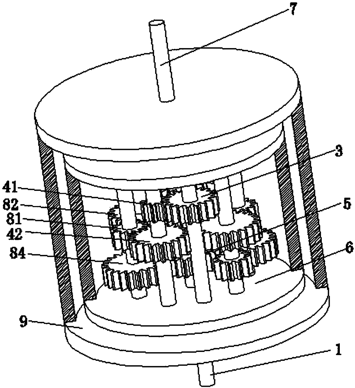
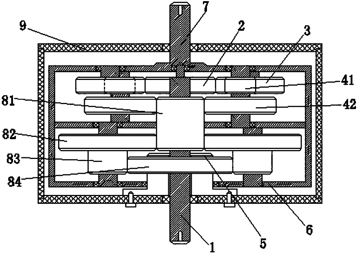
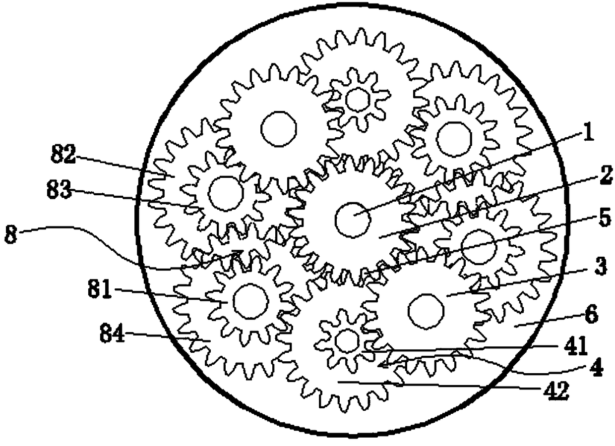
[0028] see figure 1 , figure 2 with image 3 ,

[0029] The housing 9 is fixed with a fixed support gear 5, the support body 6 is rotationally connected with the housing, the fixed support gear 5 is coaxially inserted with the input shaft 1, the input shaft 1 is provided with a central drive gear 2, and the central drive gear 2 is connected to the bridge The gear 3 is driven on the same layer, and the bridge gear 3 drives the bridge speed-up gear set 4, wherein the bridge gear 3 and the upper bridge gear 41 are driven on the same layer, and the upper bridge gear 41 and the lower bridge gear 42 are coaxially fixed And it can be driven synchronously, the lower bridge gear 42 drives the reduction gear set 8, the reduction gear set includes the first gear 81, the second gear 82, the third gear 83 and the fourth gear 84, the first gear 81 and the second gear 82 are the same Layer transmission, the second gear 82 and the third gear 83 are coaxially fixed and driven synchronously...

Embodiment 2

[0035] see Figure 5 with Image 6 , the illustrated embodiment is the input mode of the ring gear, in the figure:

[0036] The casing 9 is fixed with a fixed support gear 5, the support frame 6 is connected to the casing in rotation, the input shaft 1 is arranged on one side of the support frame 6, and the input shaft 1 is fixed with a drive wheel 10, and the drive wheel 10 is connected to the drive ring gear 2' The outer circumference of the drive ring gear 2' is also provided with teeth, and the teeth on the inner circumference of the drive ring gear 2' are transmitted on the same layer as the bridge gear 3, and the bridge gear 3 is driven to overlap the bridge gear set 4. Wherein, the bridge gear 3 and the upper bridge gear 41 are transmitted on the same layer, the upper bridge gear 41 and the lower bridge gear 42 are coaxially fixed and can be driven synchronously, and the lower bridge gear 42 drives a reduction gear set, and the reduction gear set includes The first ge...


PUM


Abstract

The invention discloses a gear transmission structure. The gear transmission structure comprises an input shaft, a carrier gear, a carrier speed increasing gear set, a speed reduction gear set, a fixed counterpressure gear, a supporting body and a shell, wherein the carrier gear, the carrier speed increasing gear set, the speed reduction gear set and the fixed counterpressure gear are arranged inthe supporting body; the fixed counterpressure gear and the carrier gear are arranged coaxially in a layered mode; the fixed counterpressure gear is fixed to the shell; the supporting body is rotationally connected with the shell; and the carrier speed increasing gear set and the speed reduction gear set are connected between the carrier gear and the fixed counterpressure gear in a transmission mode. According to the gear transmission structure, the speed reduction gear set and the carrier speed increasing gear set are arranged, the gear friction resistance is balanced, output is carried out in cooperation with the fixed counterpressure gear, and the overall operation efficiency of the mechanism is improved.

Description

technical field [0001] The invention relates to the field of mechanical transmission devices, in particular to a gear transmission structure. Background technique [0002] In the mechanical field, the use of gears is quite extensive. When the gear and the gear mesh to transmit speed and torque, when the large gear drives the small gear, the speed of the small gear will increase, but the driving force given by the large gear is greater than the output force of the small gear; if the small gear is used to drive the large gear, the large gear will The speed of the gear will decrease, but the driving force given by the small gear is less than the output force of the large gear. In order to maintain a high torque, the rotational speed needs to be reduced accordingly, and the transmission efficiency of the structure of the prior art is low, and technical personnel in the industry generally want to improve the transmission efficiency of the existing gear transmission structure. ...

Claims


Application Information

Patent Timeline
Patent Type & Authority Applications(China)
IPC IPC(8): F16H1/22
CPCF16H1/22
Inventor 何晓明
Owner 何晓明
Why Eureka
Try Eureka