
A bridge hoisting device

A technology for hoisting equipment and bridges, applied in hoisting devices, spring mechanisms, etc., can solve problems such as poor stability, slow speed, and troublesome replacement of rope shafts, and achieve improved stability, reduced energy consumption and cost, and simple structure Effect

Active Publication Date: 2020-07-17
ANHUI WEIHONG STEEL STRUCTURE GRP
View PDF5 Cites 0 Cited by
  • Summary
  • Abstract
  • Description
  • Claims
  • Application Information

AI Technical Summary

Problems solved by technology

Traditional man-made cable hoisting is time-consuming, laborious, poor in stability, and slow in speed; large cranes are bulky and unsuitable in many occasions where space is insufficient; some automatic rope-retracting equipment uses a turntable to retract the rope when retracting the rope, but these devices often There will be uneven distribution of the suspension rope on the rope reel, which greatly affects the stability of the rope collection, and it is very troublesome to replace the rope shaft

Method used


Image

  • A bridge hoisting device
  • A bridge hoisting device
  • A bridge hoisting device

Examples


Embodiment Construction

[0018] The following will clearly and completely describe the technical solutions in the embodiments of the present invention with reference to the accompanying drawings in the embodiments of the present invention. Obviously, the described embodiments are only some, not all, embodiments of the present invention. Based on the embodiments of the present invention, all other embodiments obtained by persons of ordinary skill in the art without making creative efforts belong to the protection scope of the present invention.

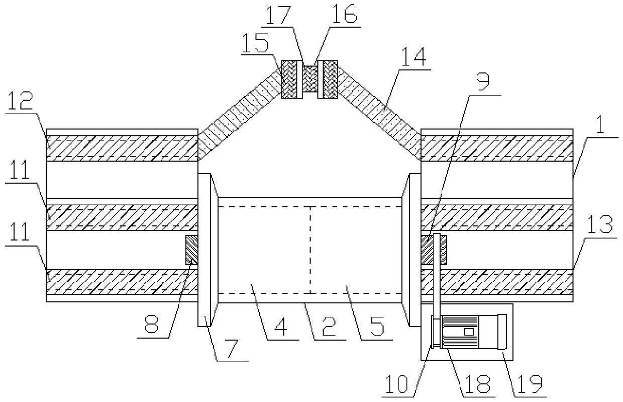
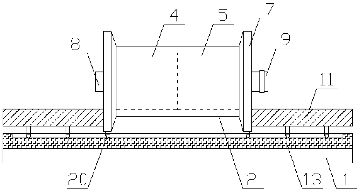
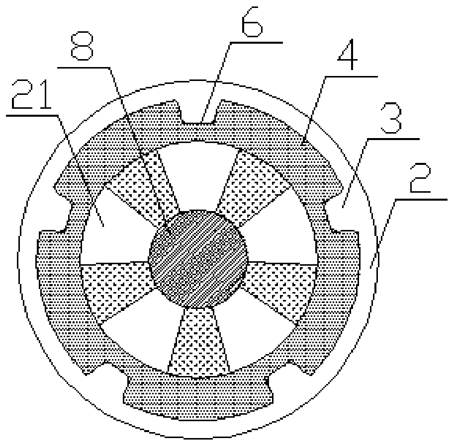
[0019] The present invention provides such Figure 1-4 The shown bridge hoisting equipment includes a base plate 1, the top of the base plate 1 is provided with a reel 2, the inner wall of the reel 2 is provided with a strip-shaped convex plate 3, and the inside of the reel 2 is provided with a second A rotating drum 4 and a second rotating drum 5, the first rotating drum 4 and the second rotating drum 5 are provided with bar-shaped chutes 6 outside, and the e...


PUM


Abstract

The invention discloses bridge hoisting equipment which comprises a base plate. A winding reel is arranged at the top of the base plate, a strip-type protruding plate is arranged on the inner wall ofthe winding reel, a first rotating barrel and a second rotating barrel are arranged inside the winding reel, strip-shaped sliding grooves are formed in the exteriors of the first rotating barrel and the second rotating barrel, baffles are arranged at the ends of the first rotating barrel and the second rotating barrel, a first rotating shaft is arranged inside the first rotating barrel, and a bossis arranged at one end of the first rotating shaft. According to the bridge hoisting equipment, the first rotating barrel and the second rotating barrel are driven by a first lead screw to move leftand right, strip-shaped protruding plates and the strip-shaped sliding grooves are movably clamped and connected, mounting and demount of the winding reel are facilitated, and the winding reel can bedriven by the first rotating barrel and the second rotating barrel to rotate for winding; and rollers are arranged at the bottoms of the first lead screw, a second lead screw and the baffles, the demounting and mounting stability of the winding reel is improved, the stability of even winding of ropes driven by a wire clamping groove is improved, a second rotating shaft and a first rotating shaft are clamped and connected, the first rotating shaft is driven by the second rotating shaft to rotate, the structure is simple, and energy consumption and cost are reduced.

Description

technical field [0001] The invention relates to the field of bridge hoisting equipment, in particular to bridge hoisting equipment. Background technique [0002] In the process of bridge construction, it is often necessary to hoist materials such as silt concrete, steel pipe fittings, etc. from a low place to the bridge through hoisting equipment. The traditional man-made cable hoisting is time-consuming, labor-intensive, poor in stability and slow in speed; large cranes are bulky and unsuitable in many occasions with insufficient space; some automatic rope-retracting devices use the turntable to reel in the rope when retrieving the rope, but these devices often There will be uneven distribution of the suspension rope on the rope reel, which greatly affects the stability of the rope collection, and it is very troublesome to replace the rope shaft. [0003] Therefore, it is necessary to invent a kind of bridge hoisting equipment to solve the above problems. Contents of the...

Claims


Application Information

Patent Timeline
Patent Type & Authority Patents(China)
IPC IPC(8): B66D1/39B66D1/12
CPCB66D1/12B66D1/39
Inventor 曹雁冰
Owner ANHUI WEIHONG STEEL STRUCTURE GRP
Learn More