Zero-bias self-calibration MEMS gyroscope, and zero-bias self-calibration method thereof

A gyroscope, self-calibration technology, applied in gyroscope/steering sensing equipment, gyro effect for speed measurement, instruments, etc., can solve the problem of gyroscope bias-temperature model prone to change, rapidity, stability, and hysteresis Affect the performance of the gyroscope, the inconsistency of the zero bias, etc.

Active Publication Date: 2018-07-06
BEIJING MXTRONICS CORP +1
View PDF4 Cites 27 Cited by
  • Summary
  • Abstract
  • Description
  • Claims
  • Application Information

AI Technical Summary

Problems solved by technology

The currently reported methods to improve the accuracy of gyroscopes mainly include temperature control and temperature compensation. However, these two methods have certain limitations in terms of design and compensation effects.
Among them, temperature control requires the design of additional temperature control components, which will increase the size and power consumption of the gyro system. In addition, the dynamic performance of the constant temperature control, such as rapidity, stability, and hysteresis, will affect the performance of the gyroscope, and there are design difficulties.
Temperature compensation needs to establish a temperature compensation model through high and low temperature te

Method used


Image

  • Zero-bias self-calibration MEMS gyroscope, and zero-bias self-calibration method thereof
  • Zero-bias self-calibration MEMS gyroscope, and zero-bias self-calibration method thereof
  • Zero-bias self-calibration MEMS gyroscope, and zero-bias self-calibration method thereof

Examples


Example Embodiment

[0042] The specific implementation manners of the MEMS gyroscope zero-bias self-calibration method based on drive / detection mode reversal of the present invention will be described with reference to the accompanying drawings and specific embodiments.
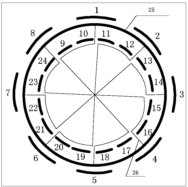
[0043] figure 1 It is a structural diagram of the resonant ring of the MEMS gyroscope in the present invention. The resonance ring 25 is fixed by an eight-part support beam 26 arranged in the circumferential direction. There are 8 electrodes evenly distributed on the outside of the resonance ring 25, which are electrode 1 to electrode 8 clockwise. Electrode 1 and electrode 5 are the driving electrodes of the driving mode, electrode 3 and electrode 7 are the detection electrodes of the driving mode, and electrodes 2 and Electrode 6 is the driving electrode of the detection mode, and electrode 4 and electrode 8 are the detection electrodes of the detection mode. When the gyroscope works in the two modes in reverse, the function of th...


PUM


Abstract

The invention a MEMS gyroscope zero-bias self-calibration method based on driving/detecting modal inversion, and the MEMS gyroscope zero-bias self-calibration method is capable of solving problems inthe prior art that drift of fully-symmetrical MEMS gyroscopes is caused and power-on zero-bias of a plurality of times is different. According to the MEMS gyroscope zero-bias self-calibration method,gyroscope working characteristics are taken into consideration, a gyroscope dynamic model is taken as a base, the change rules of two working modes before and after driving modal and detecting modal inversion are given, switch of the circular gyroscope between the two working mode is realized using a signal processing circuit. The difference of the detection signals at the adjacent working modes is obtained, so that MEMS circular gyroscope zero-bias self-calibration is realized at last. The MEMS gyroscope zero-bias self-calibration method is capable of extracting zero-bias signals effectively,inhibiting zero-bias drift, and increasing the precision of the MEMS circular gyroscopes.

Description

technical field [0001] The invention relates to a MEMS gyroscope zero-bias self-calibration method, in particular to a MEMS gyroscope zero-bias self-calibration method based on drive / detection mode inversion, which is suitable for a structurally symmetrical MEMS ring gyroscope to realize zero-bias online self-calibration. calibration. Background technique [0002] As an important inertial device, MEMS gyroscope has the advantages of small size, low power consumption, low cost, strong anti-overload ability, etc., and has a wide range of applications. However, the performance of MEMS gyroscopes is affected by various factors such as process errors and the environment, resulting in problems such as zero bias in the output, easy drift of zero bias, and inconsistent zero bias after multiple power-on. The signal is extracted from the useful angular velocity signal, which limits its application. [0003] Temperature is an important factor affecting the accuracy of MEMS gyroscopes...

Claims


Application Information

Patent Timeline
IPC IPC(8): G01C19/56G01C19/5776G01C25/00
CPCG01C19/56G01C19/5776G01C25/005
Inventor 康苗苗柴宏玉王恪良周博远熊开利权海洋
Owner BEIJING MXTRONICS CORP
Why Eureka
Try Eureka