
Bionic optical imaging system

An imaging system and bionic optics technology, applied in the field of bionic optical imaging systems, can solve the problems of poor imaging quality, structural interference, vignetting, etc., and achieve the effects of reducing vignetting, preventing interference phenomenon, and good uniformity of illumination

Pending Publication Date: 2018-07-06
LUOYANG INST OF ELECTRO OPTICAL EQUIP OF AVIC
View PDF1 Cites 3 Cited by
  • Summary
  • Abstract
  • Description
  • Claims
  • Application Information

AI Technical Summary

Problems solved by technology

[0008] The purpose of the present invention is to provide a bionic optical imaging system to solve the problem of poor imaging quality caused by structural interference and vignetting at the edge of the collected image in the existing large-field-of-view high-resolution optical imaging system

Method used


Image

  • Bionic optical imaging system
  • Bionic optical imaging system
  • Bionic optical imaging system

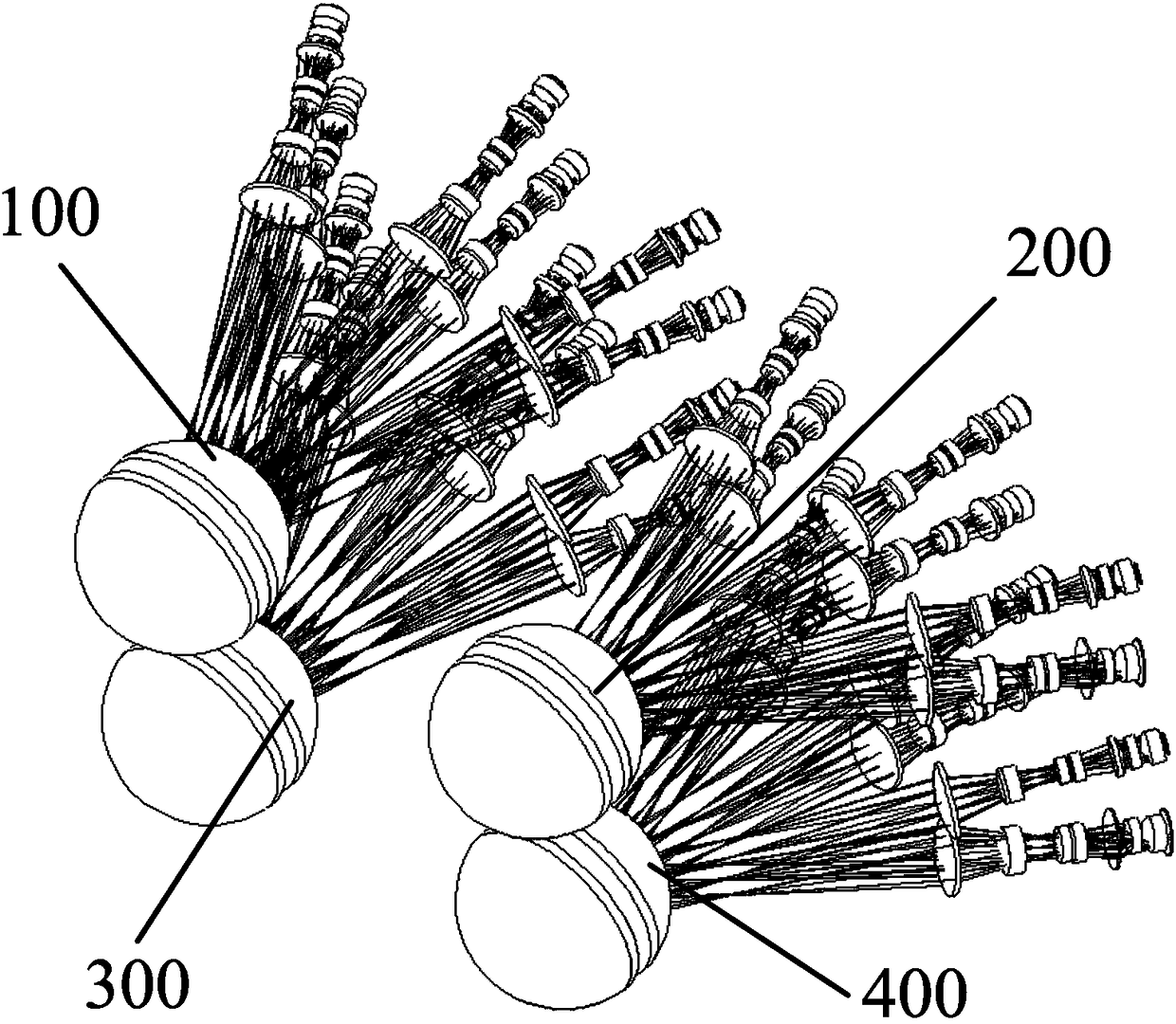
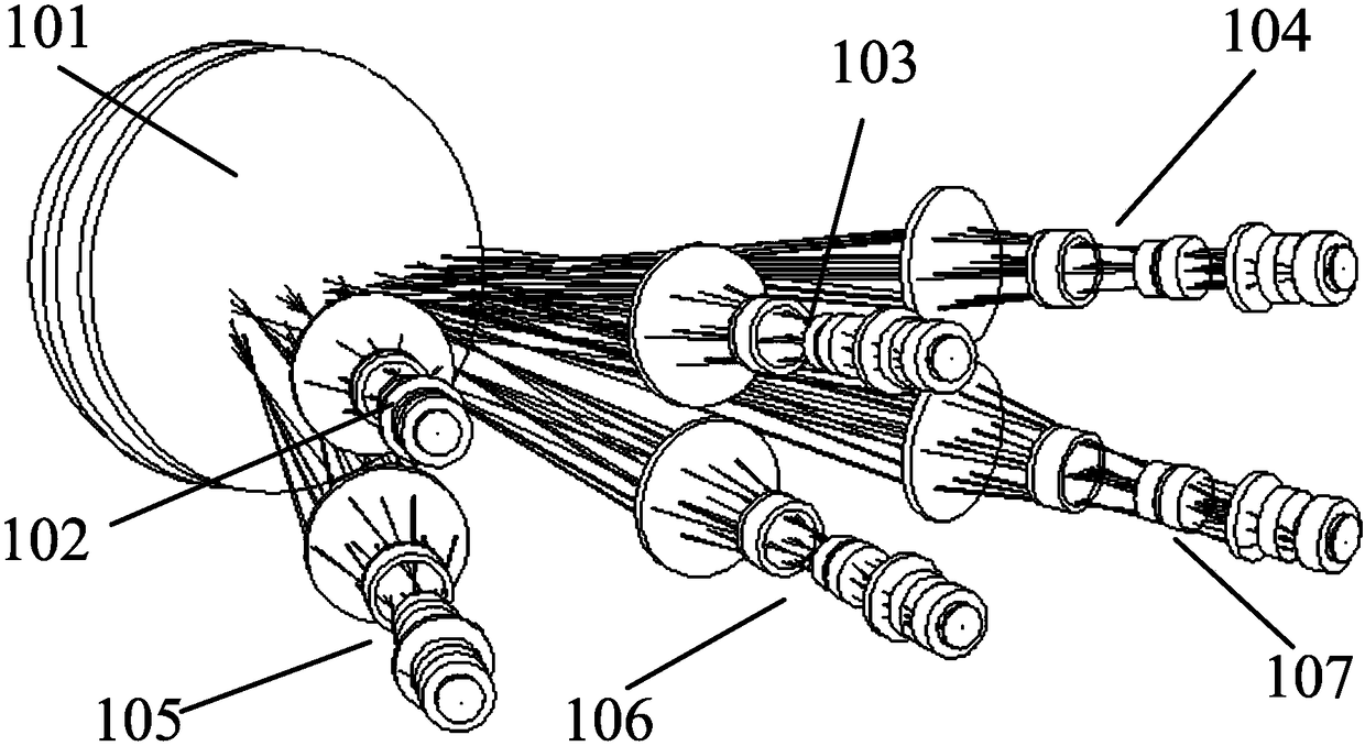
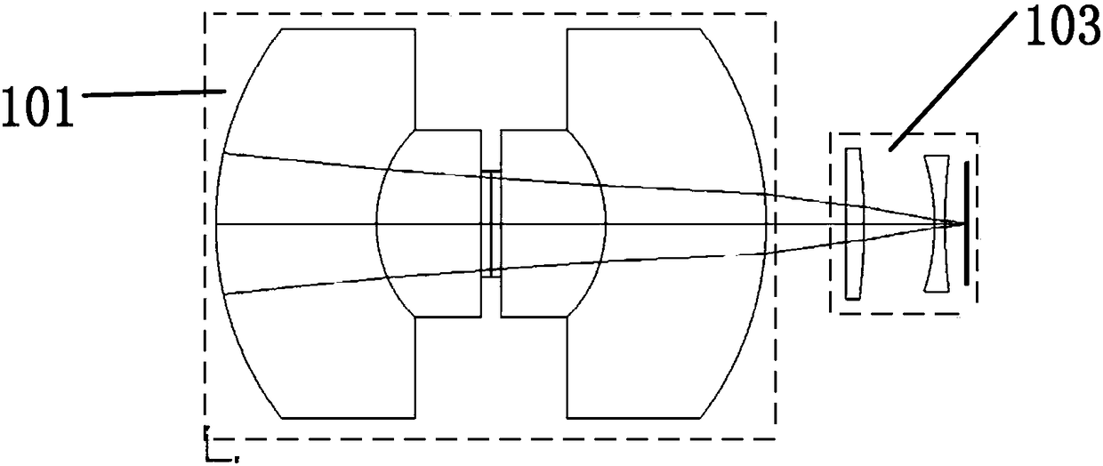
Examples


Embodiment Construction

[0023] The present invention will be described in further detail below in conjunction with the accompanying drawings.

[0024] The invention provides a bionic optical imaging system, which uses the principle of bionic optical compound eye imaging and uses multiple subsystems, each of which includes a concentric sphere objective lens and multiple sub-aperture cameras, through cross-overlapping of fields of view and later image splicing processing , to achieve wide-angle high-definition imaging, taking advantage of the imaging characteristics of concentric spherical objective lens to rotate symmetrically along the center of the sphere, by simply copying the optical path design and changing a small number of parameters, multiple sub-systems can be designed side by side, and the system design and structure can be kept simple. The positions of the sub-aperture cameras in each subsystem are fixed, no scanning mechanism is required, the subsequent software and hardware processing syst...


PUM


Abstract

The invention relates to the field of large-field-of-view and high-resolution imaging technology, in particular to a bionic optical imaging system. The imaging system comprises at least two subsystems, each subsystem comprises a concentric spherical objective lens and at least two sub-aperture cameras, and the optical axis of each sub-aperture camera of each subsystem passes through the center ofthe concentric spherical objective lens of the corresponding subsystem. Field angles are set at intervals for images captured by the sub-aperture cameras, and the vacant parts of the field angles setat intervals are complemented by image overlapping of the subsystems and are continuous within the set field of view, so that the adjacent sub-aperture cameras are spaced a certain angle, the interference between the sub-apertures is effectively prevented, vignetting of the imaging system is reduced, the imaging system has good illumination uniformity in the field of view, and the problems of lowimaging quality, difficult stitching and the like caused by structural interference and vignetting of the edge field of view of the acquired image in the existing large-field-of-view and high-resolution optical imaging system are solved.

Description

technical field [0001] The invention relates to the technical field of large-field-of-view and high-resolution imaging, in particular to a bionic optical imaging system. Background technique [0002] Compared with radar, optical imaging equipment has the characteristics of high resolution, visualization, and passive detection, so it is widely used in various fields such as surveillance, investigation, and search and rescue. Suppose the field of view of the optical system is θ, the angular resolution is γ, the imaging field of view is outside the rectangular photosensitive surface of the image sensor, and the number of pixels on a single side of the image sensor is N H ×N V , then there is: [0003] [0004] It can be seen from this that when the image sensor is selected (N H with N V is a fixed value), the smaller the value of γ (that is, the higher the angular resolution), the smaller the value of θ (that is, the smaller the angle of view), and the angle of view is l...

Claims


Application Information

Patent Timeline
IPC IPC(8): H04N5/225H04N5/232H04N5/247G02B27/58
CPCG02B27/58H04N23/50H04N23/55H04N23/45H04N23/951H04N23/90
Inventor 陈水忠刘佳
Owner LUOYANG INST OF ELECTRO OPTICAL EQUIP OF AVIC
Learn More