
3D printer spraying nozzle structure

A 3D printing and nozzle technology, applied in coating devices, additive processing, etc., can solve problems such as high personnel requirements, complex 3D printing model structure, affecting 3D printing applications, etc., to achieve the effect of improving production efficiency

Inactive Publication Date: 2018-07-10
CHENGDU YUYUE TECH CO LTD
View PDF0 Cites 0 Cited by
  • Summary
  • Abstract
  • Description
  • Claims
  • Application Information

AI Technical Summary

Problems solved by technology

[0002] In recent years, 3D printers have become more and more popular, but due to the constraints of the molding process and molding speed, the spatial positioning of the current 3D printers is based on the three-dimensional coordinates X, Y, and Z. If a circular model is printed on the same plane, 3D It is difficult for the model printed by the printer to overcome the layered texture formed in the Z-axis direction. At the same time, there is no way to effectively choose the radius of the circular model. It can only be achieved by replacing the connecting column to achieve the ideal size, which is extremely inconvenient. This is very inconvenient for 3D printers. Wide application in industrial and civil markets is subject to certain restrictions
The traditional processing of 3D printing models is through the steps of dusting, grinding, and color spraying. However, due to the general structure of 3D printing models, it is time-consuming to process, and it has high requirements for personnel and low efficiency, which seriously affects Application of 3d printing in civilian market

Method used


Image

  • 3D printer spraying nozzle structure
  • 3D printer spraying nozzle structure

Examples


Embodiment Construction

[0011] The present invention will be further elaborated below in conjunction with the accompanying drawings and specific embodiments.

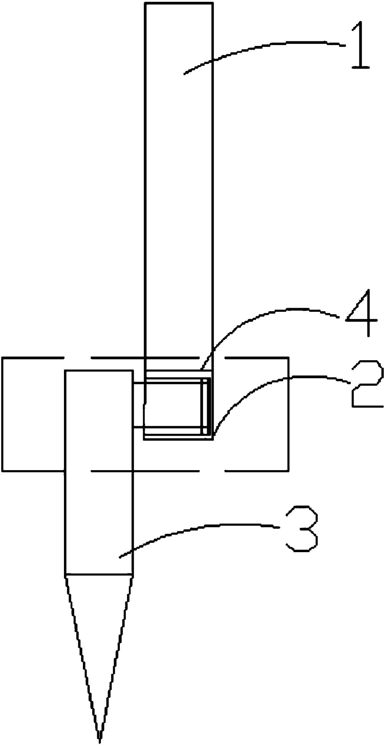
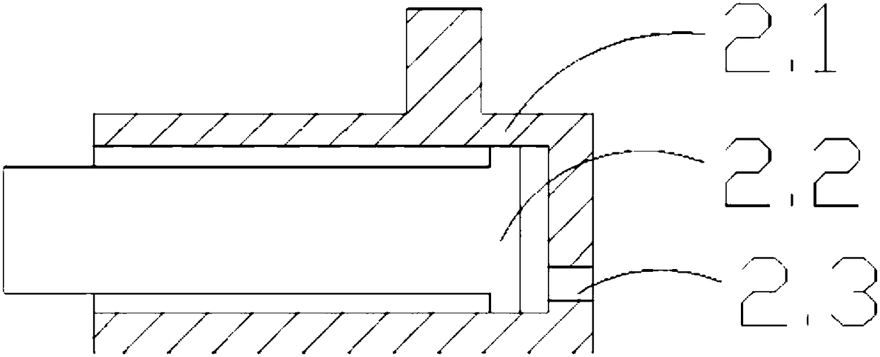
[0012] Such as figure 1 and 2 As shown, a 3D printing nozzle structure includes a main connecting column 1, a secondary connecting column 2 and a nozzle 3, the lower end of the main connecting column 1 is provided with a bearing 4, the bearing 4 is a deep groove ball bearing, and the main connecting column 1 The bearing 4 is connected to one end of the auxiliary connecting column 2; the upper part of the outer body 2.1 is provided with a protruding shaft that cooperates with the inner ring of the bearing 4; the auxiliary connecting column 2 rotates 360° around the axis of the main connecting column in (X, Z ) is to print a circular model on the base surface, the secondary connecting column 2 includes an outer body 2.1, a piston movable rod 2.2 and an air hole 2.3, the piston movable rod 2.2 is arranged in the cavity of the outer body 2.1, and...


PUM


Abstract

The invention provides a 3D printer spraying nozzle structure, which comprises a main connection column, a secondary connection column and a spraying nozzle, wherein the lower end of the main connection column is provided with a bearing, the main connection column is connected to one end of the secondary connection column through the bearing, the secondary connection column comprises an outer body, a piston movement rod and a gas hole, the piston movement rod is arranged in the molding cavity of the outer body, the gas hole is arranged at the bottom portion of the molding cavity of the outer body, and the gas hole is communicated to the molding cavity of the outer body. According to the present invention, the secondary connection column can rotate 360 DEG by using the axial line of the main connection column as the center, such that the printed model can overcome the stacked texture formed in the Z-axis direction; and the secondary connection column is the stretching movement rod, suchthat the radius of the circular model can be automatically adjusted by the machined according to the actual needs in the printing work so as to improve the production efficiency.

Description

technical field [0001] The invention belongs to the field of 3D advanced manufacturing, and in particular relates to a 3D printing nozzle structure. Background technique [0002] In recent years, 3D printers have become more and more popular, but due to the constraints of the molding process and molding speed, the spatial positioning of the current 3D printers is based on the three-dimensional coordinates X, Y, and Z. If a circular model is printed on the same plane, 3D It is difficult for the model printed by the printer to overcome the layered texture formed in the Z-axis direction. At the same time, there is no way to effectively choose the radius of the circular model. It can only be achieved by replacing the connecting column to achieve the ideal size, which is extremely inconvenient. Wide application in industrial and civil markets is subject to certain constraints. The traditional processing of 3D printing models is through the steps of dusting, grinding, and color s...

Claims


Application Information

Patent Timeline
IPC IPC(8): B29C64/209B33Y30/00
CPCB33Y30/00
Inventor 不公告发明人
Owner CHENGDU YUYUE TECH CO LTD
Features
  • Generate Ideas
  • Intellectual Property
  • Life Sciences
  • Materials
  • Tech Scout
  • Unparalleled Data Quality
  • Higher Quality Content
  • 60% Fewer Hallucinations
Learn More