
Electrical connector and manufacturing method thereof

A technology of an electrical connector and a manufacturing method, which is applied in the connection, the manufacture of the contact box/base, and the two-part connection device, etc., can solve the problems of waste of cost, manpower, and complicated operation, and achieve the effect of ensuring the grounding effect.

Active Publication Date: 2020-05-19
FOXCONN (KUNSHAN) COMPUTER CONNECTOR CO LTD +1
View PDF6 Cites 0 Cited by
  • Summary
  • Abstract
  • Description
  • Claims
  • Application Information

AI Technical Summary

Problems solved by technology

[0002] In the prior art, the Type C connector has two upper and lower rows of conductive terminals, a pair of shielding sheets and overlapping terminals clamped between the upper and lower rows of conductive terminals, and the shielding sheet is electrically connected to the grounding terminals of the upper and lower rows of conductive terminals. To enhance the grounding effect of the electrical connector, the overlapping terminals are electrically connected to the power terminals of the upper and lower rows of conductive terminals to transmit large currents. However, shielding sheets and overlapping terminals need to be formed separately during the molding process. Complicated operation, waste of cost and manpower

Method used


Image

  • Electrical connector and manufacturing method thereof
  • Electrical connector and manufacturing method thereof
  • Electrical connector and manufacturing method thereof

Examples


Embodiment Construction

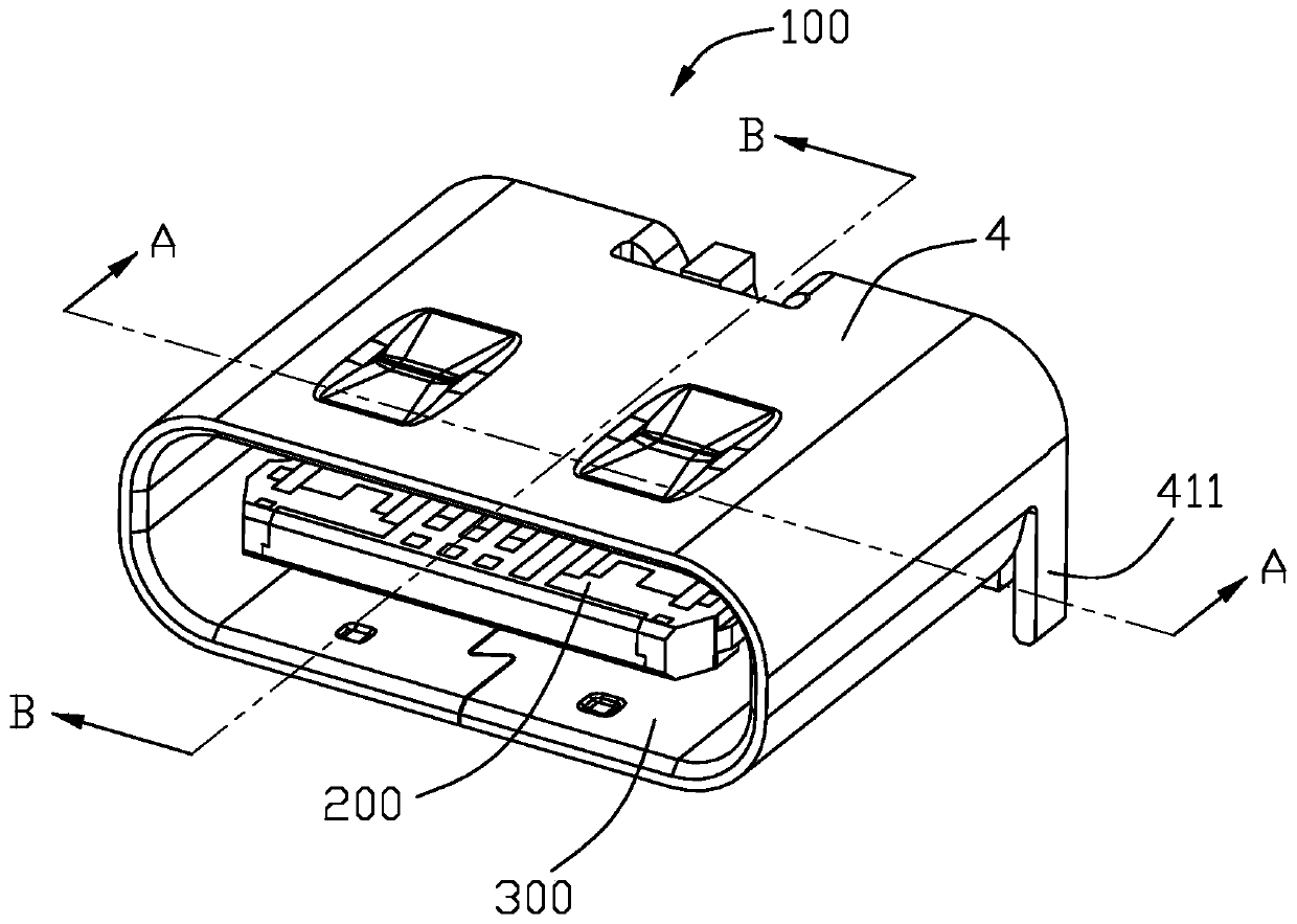
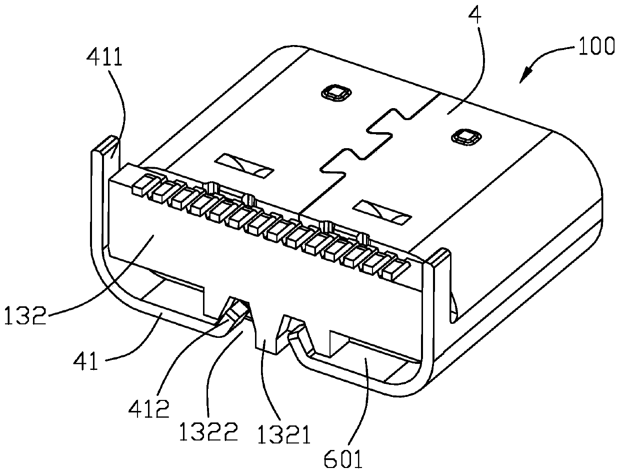
[0053] Below, will combine Figure 1 to Figure 13 A specific implementation manner of the electrical connector 100 of the present invention is introduced. A port where the electrical connector 100 is plugged into a mating connector (not shown) is defined as a plugging end. Define the plug-in end as the front end, and the plug-in direction as the front-rear direction.

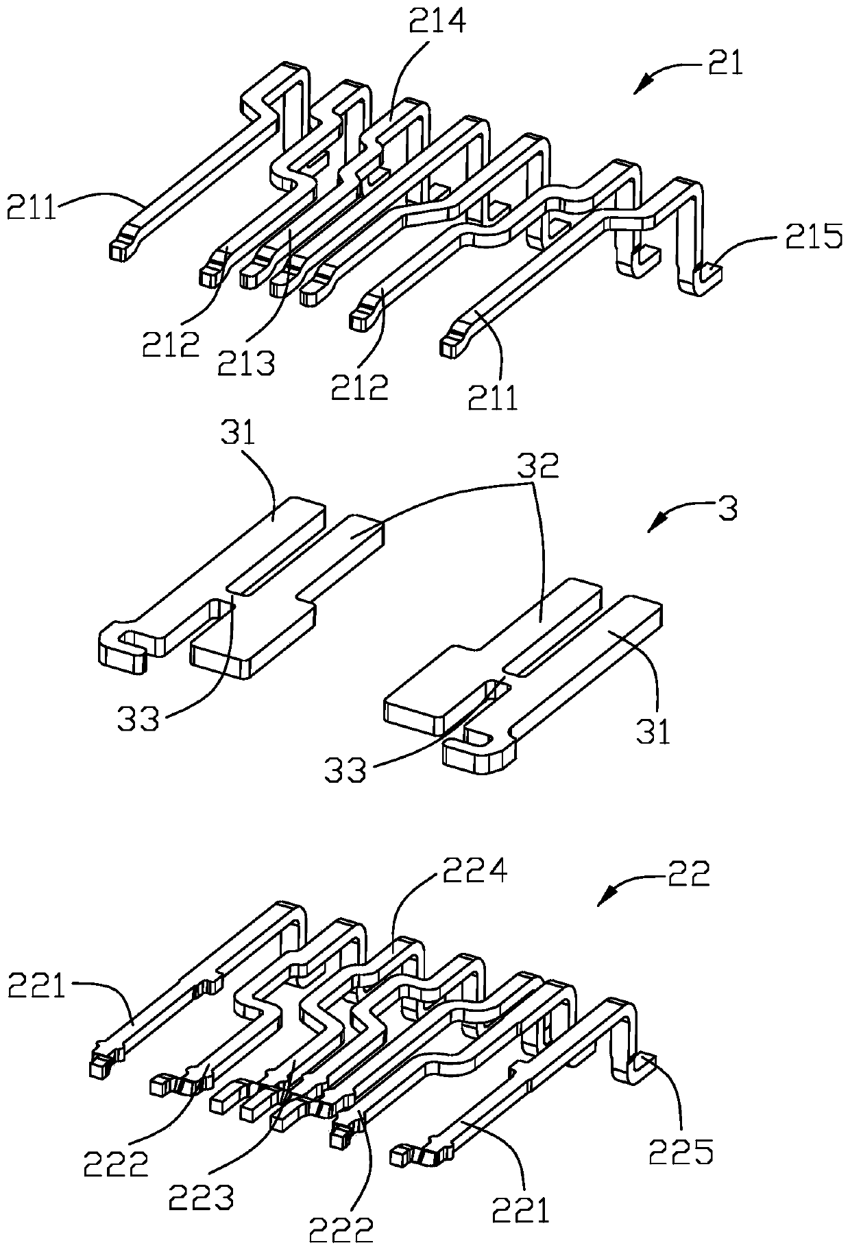
[0054] Please refer to Figure 1 to Figure 11 As shown, the present invention provides an electrical connector 100 , including a terminal module 200 , a shielding case 4 and a waterproof rubber plate 5 sheathed outside the terminal module 200 . The terminal module 200 includes an insulating body 1 , two rows of conductive terminals 2 held in the insulating body 1 , and a metal sheet 3 clamped between the two rows of conductive terminals 2 .

[0055] Please refer to Figure 5 to Figure 11As shown, the insulating body 1 includes a base 11 and a tongue 12 extending forward from the base 11 . The insulating bod...


PUM


Abstract

The present invention provides an electrical connector, which includes a terminal module and a shielding shell sleeved outside the terminal module. The terminal module includes an insulating body and two rows of conductive terminals held in the insulating body. and the metal sheet clamped between the upper and lower rows of conductive terminals, the insulating body further includes a first insulating body, and the upper and lower rows of conductive terminals include grounding terminals on the outside and power terminals on the inside of the grounding terminals, The metal sheet has a first shielding sheet clamped between the ground terminals of the upper and lower rows of conductive terminals and a second shielding sheet clamped between the power terminals of the upper and lower rows of conductive terminals. An insulating body is injection-molded outside the upper and lower rows of conductive terminals and the metal sheet, and corresponding to the position between the first shielding sheet and the second shielding sheet, a cutout of the first shielding sheet and the second shielding sheet is formed. Cut the separate cutouts.

Description

【Technical field】 [0001] The invention relates to an electrical connector and a manufacturing method thereof, in particular to an electrical connector suitable for front and back insertion and a manufacturing method thereof. 【Background technique】 [0002] In the prior art, the Type C connector has two upper and lower rows of conductive terminals, a pair of shielding sheets and overlapping terminals clamped between the upper and lower rows of conductive terminals, and the shielding sheet is electrically connected to the grounding terminals of the upper and lower rows of conductive terminals. To enhance the grounding effect of the electrical connector, the overlapping terminals are electrically connected to the power terminals of the upper and lower rows of conductive terminals to transmit large currents. However, shielding sheets and overlapping terminals need to be formed separately during the molding process. Complicated operation, waste of cost and manpower. [0003] The...

Claims


Application Information

Patent Timeline
Patent Type & Authority Patents(China)
IPC IPC(8): H01R13/6585H01R13/40H01R43/20
CPCH01R13/40H01R13/6585H01R43/20H01R13/6581H01R43/24H01R2107/00H01R24/60H01R43/18
Inventor 赵俊
Owner FOXCONN (KUNSHAN) COMPUTER CONNECTOR CO LTD
Learn More