Clamp applicable to machine tools

A technology for fixtures and machine tools, applied in the field of fixtures for machine tools, can solve problems such as difficulty in realizing rotating operations, and achieve the effect of ensuring compactness, small size, and easy assembly.

Inactive Publication Date: 2018-07-13
YANGTZE NORMAL UNIVERSITY
View PDF8 Cites 18 Cited by
  • Summary
  • Abstract
  • Description
  • Claims
  • Application Information

AI Technical Summary

Problems solved by technology

[0004] However, the above-mentioned "a jig for cutting and/or grinding processing of shaft parts" still has the disadvantage that it is difficult to realize the rotati

Method used


Image

  • Clamp applicable to machine tools
  • Clamp applicable to machine tools
  • Clamp applicable to machine tools

Examples


Example Embodiment

[0066] The present invention will be further described in detail below in conjunction with the drawings. Among them, descriptive terms such as up, down, left, and right are used for the description, which aims to help readers understand, and are not intended to limit.

[0067] The first embodiment, such as Figure 2 to Figure 6 Shown:
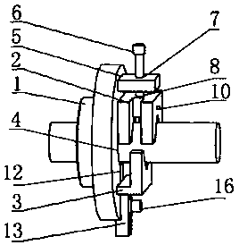
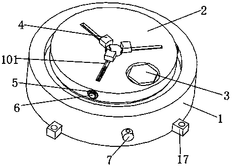
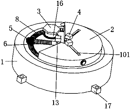
[0068] A clamp for a machine tool, comprising a clamping table 2 and a clamping mechanism; the middle of the clamping table 2 is provided with a hole for inserting the end of the shaft part, and a clamping table 2 beside the hole A clamping mechanism for clamping shaft parts is installed on the table surface; the clamping mechanism includes a clamping block 4 and a clamping block driving structure. The clamping blocks 4 are at least two evenly spaced in the circumferential direction of the jack , And each block 4 can reciprocate close to or away from the socket in the radial direction of the socket under the drive of the block driving structure;

...


PUM


Abstract

The invention discloses a clamp applicable to machine tools. The clamp applicable to the machine tools comprises a clamping table and a clamping mechanism, the clamping mechanism comprises at least two clamping blocks and a clamping block drive structure, and the clamping blocks are arranged in the circumference direction of an insertion hole at even intervals. The clamp applicable to the machinetool is characterized by further comprising a rotation drive mechanism for driving the clamping table to rotate; the rotation drive mechanism comprises a base, a rotation drive rod, a rotation drive gear and a rotation driven connecting piece; the rotation drive rod is rotationally installed on the base, one end of the rotation drive rod is a rotation drive end, and a rotation drive gear is coaxially fixed to the other end of the rotation drive rod; and the lower surface of the clamping table is rotationally connected with the base, and the rotation driven connecting piece is fixedly installedto the lower surface of the clamping table and connected with the rotation drive gear in an engaged mode. The clamp applicable to the machine tools has the clamping and rotating functions and furtherhas the advantage of simple, compact and reasonable structure.

Description

technical field [0001] The invention belongs to the field of fixtures, and in particular relates to a fixture for machine tools. Background technique [0002] Shaft parts are a kind of parts that are often processed by machine tools. At present, most shaft parts are processed by lathes first, and then need to be reprocessed; however, there are many types of machine tools required for reprocessing shaft parts, such as milling machines, drilling machines, grinding machines, etc. However, Except for lathes, there is no fixture specially used for clamping shaft parts similar to lathes on other machine tools, so it is difficult to quickly clamp and position shaft parts. [0003] In the prior art, the patent with the notification number CN203600067U discloses "a jig for cutting and / or grinding processing of shaft parts", which "a jig for cutting and / or grinding processing of shaft parts" (see the attached figure 1 ) includes a chuck 1, an upper chuck 2 and a lower chuck 3, the m...

Claims


Application Information

Patent Timeline
IPC IPC(8): B23Q3/06
Inventor 田务林牛刚
Owner YANGTZE NORMAL UNIVERSITY
Why Eureka
Try Eureka