
New energy automobile seat

A new energy vehicle and seat technology, applied in vehicle seats, vehicle parts, special positions of vehicles, etc., can solve problems such as affecting driving, high usage limitations, and potential safety hazards, so as to improve usage limitations and improve adaptability. ability, the effect of reducing security risks

Inactive Publication Date: 2018-07-13
山西云度知识产权服务有限公司
View PDF10 Cites 2 Cited by
  • Summary
  • Abstract
  • Description
  • Claims
  • Application Information

AI Technical Summary

Problems solved by technology

[0002] As we all know, the new energy car seat is an important accessory device used in the interior of new energy vehicles to provide seats for the driver and other passengers, and to ensure the safety and comfort of the driver and other passengers. It is used in automotive supplies and safety It has been widely used in the field; the existing new energy car seat includes a base, a backrest and a headrest, the backrest is installed on the right outer wall of the base, and the bottom end of the backrest is flush with the bottom end of the base, and the headrest is installed At the top of the backrest; when using the existing new energy car seat, first adjust the seat to the driver's suitable driving position, then adjust the inclination of the backrest, and finally adjust the position of the headrest; the existing new energy car seat During the use of the chair, it was found that due to the limited adjustment accuracy of the seat, it cannot be suitable for all people, resulting in pain in the waist of the driver during long-term driving, affecting driving, posing potential safety hazards, poor adaptability, and high use limitations

Method used


Image

  • New energy automobile seat
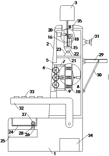
  • New energy automobile seat
  • New energy automobile seat

Examples


Embodiment Construction

[0020] The specific implementation manners of the present invention will be further described in detail below in conjunction with the accompanying drawings and embodiments. The following examples are used to illustrate the present invention, but are not intended to limit the scope of the present invention.

[0021] Such as Figure 1 to Figure 5 As shown, a new energy car seat of the present invention includes a base 1

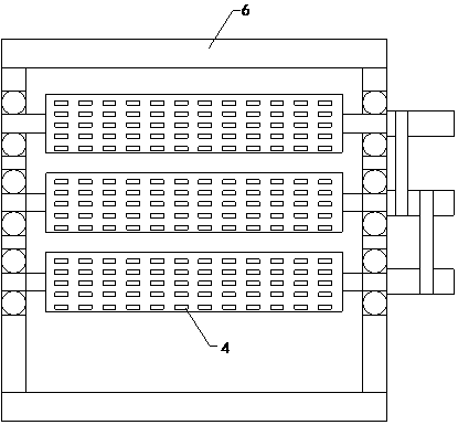
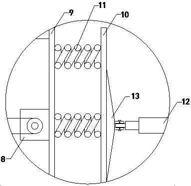
[0022], backrest 2 and headrest 3, the backrest is installed on the right outer wall of the base, and the bottom end of the backrest is flush with the bottom end of the base, and the headrest is installed on the top of the backrest; including three groups of massage rollers 4, front pole 5 , rear support rod, upper connecting rod 6, lower connecting rod, upper top plate 7, lower base plate and rotating motor 8, a working cavity is arranged inside the backrest, and the tops of the front supporting rod and the rear supporting rod are connected with the front sid...


PUM


Abstract

The invention relates to the technical field of automotive accessory devices, and particularly relates to a new energy automobile seat. A backrest can alleviate the pain of the back of a driver and relieve fatigue to reduce safety hazards, improve adaptability and improve use limitation. The automobile seat includes a base, the backrest and a headrest, and further includes three sets of massage rollers, a front supporting rod, a rear supporting rod, an upper connecting rod, a lower connecting rod, an upper top plate, a lower bottom plate and a rotating motor; a working chamber is formed in thebackrest, a right side plate is arranged on the rear ends of the upper top plate and the lower bottom plate, a baffle is arranged at the right side of the right side plate, spring groups are arrangedbetween the baffle and the right side plate, a first double acting hydraulic cylinder and a second double acting hydraulic cylinder are further arranged on the right end of the baffle, a first hingering and a second hinge ring are respectively arranged on the front end and the rear end of the right side wall of the baffle, and right ends of the first double acting hydraulic cylinder and the second double acting hydraulic cylinder are connected with the front and rear sides of the right side inner wall of the working chamber of the backrest.

Description

technical field [0001] The invention relates to the technical field of accessories for automobile supplies, in particular to a new energy automobile seat. Background technique [0002] As we all know, the new energy car seat is an important accessory device used in the interior of new energy vehicles to provide seats for the driver and other passengers, and to ensure the safety and comfort of the driver and other passengers. It is used in automotive supplies and safety It has been widely used in the field; the existing new energy car seat includes a base, a backrest and a headrest, the backrest is installed on the right outer wall of the base, and the bottom end of the backrest is flush with the bottom end of the base, and the headrest is installed At the top of the backrest; when using the existing new energy car seat, first adjust the seat to the driver's suitable driving position, then adjust the inclination of the backrest, and finally adjust the position of the headrest...

Claims


Application Information

Patent Timeline
Patent Type & Authority Applications(China)
IPC IPC(8): B60N2/90
Inventor 李有花
Owner 山西云度知识产权服务有限公司
Learn More