
Automobile part automatic annealing device

A technology for auto parts and annealing devices, which is applied to heat treatment equipment, furnaces, heat treatment furnaces, etc., can solve the problems of high production cost of automatic annealing devices, unfavorable industrial promotion and application, etc., to shorten the process temperature time, reduce heat consumption, and reduce heat dissipation effect

Active Publication Date: 2018-07-17
宁波鑫神泽汽车零部件有限公司
View PDF4 Cites 1 Cited by
  • Summary
  • Abstract
  • Description
  • Claims
  • Application Information

AI Technical Summary

Problems solved by technology

[0005] The purpose of the present invention is to provide an automatic annealing device for auto parts to solve the problem that the automatic annealing device for auto parts has a high production cost and is not conducive to industrial popularization and application

Method used


Image

  • Automobile part automatic annealing device

Examples


Embodiment Construction

[0019] The present invention will be described in further detail below by means of specific embodiments:

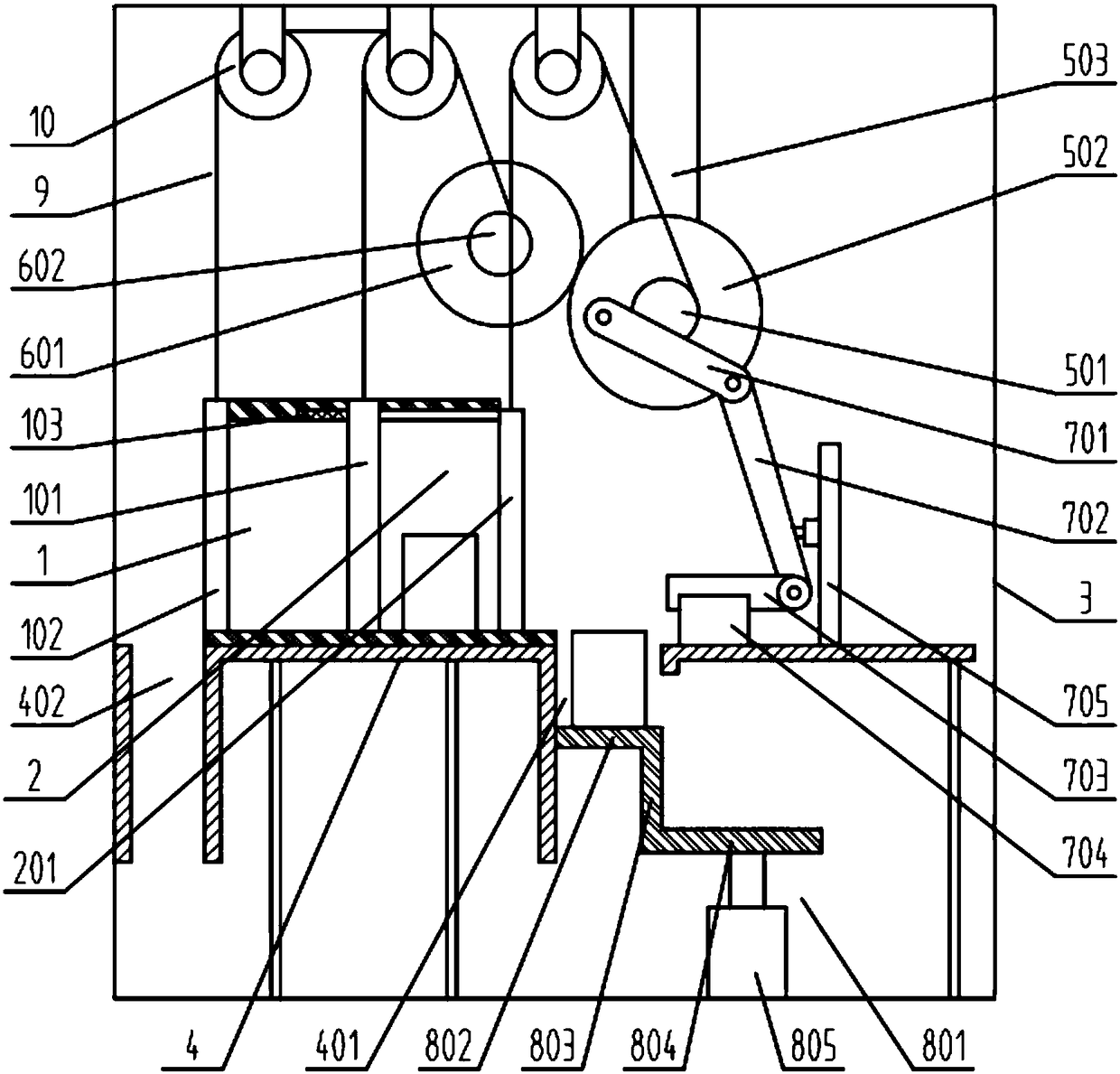
[0020] The reference signs in the accompanying drawings of the description include: working chamber 1, feed door 101, discharge door 102, elastic member 103, feed cavity 2, push door 201, box body 3, base 4, feed chute 401, discharge Material trough 402, first rotating shaft 501, driving runner 502, first support rod 503, first transmission wheel 601, second rotating shaft 602, first connecting rod 701, second connecting rod 702, horizontal push rod 703, Limiting slot 704 , vertical rod 705 , lifting platform 801 , first horizontal part 802 , vertical part 803 , second horizontal part 804 , power cylinder 805 , transmission rope 9 , steering wheel mechanism 10 .

[0021] Such as figure 1 As shown, the automatic annealing device for auto parts includes a box body 3 with an annealing chamber. The annealing chamber includes a working chamber 1 and a feeding chamber 2 with e...


PUM


Abstract

The invention belongs to the technical field of annealing device, in particular to an automobile part automatic annealing device. The automobile part automatic annealing device comprises a box body provided with an annealing chamber. The annealing chamber comprises a working chamber and a feeding chamber. A feeding door is vertically connected with one end of the working chamber in a sliding manner. A discharging door is vertically connected with the other end of the working chamber in a sliding manner. A pushing door is arranged at the front end of the feeding chamber. An elastic part is arranged on the top of the working chamber. A base is arranged below the box body. A feeding groove and a discharging groove are formed in the base. A driving wheel mechanism, a first transmission wheel mechanism, a horizontal pushing mechanism and a vertical pushing mechanism are arranged in the box body. The horizontal pushing mechanism comprises a linkage part, a horizontal pushing rod and a limiting groove. The vertical pushing mechanism comprises a lifting platform and a power cylinder. The automobile part automatic annealing device is low in production cost and high in automatic feeding anddischarging speed.

Description

technical field [0001] The invention belongs to the technical field of annealing devices, and specifically discloses an automatic annealing device for auto parts. Background technique [0002] Annealing is a metal heat treatment process. It is to slowly heat the metal to a certain temperature, keep it for a sufficient time, and then cool it at an appropriate speed. The purpose is to reduce the hardness, improve the machinability, eliminate residual stress, stabilize the size, and reduce the tendency of deformation and cracks; Refining the grain, adjusting the structure, and eliminating the defects of the structure. To be precise, annealing is a heat treatment process for metallic or non-metallic materials. In the annealing process of the workpiece, the existing annealing room mostly adopts manual control methods, such as manually controlling the opening and closing of the annealing room door, manually monitoring the real-time temperature of the annealing room, annealing tim...

Claims


Application Information

Patent Timeline
Patent Type & Authority Applications(China)
IPC IPC(8): C21D1/26C21D9/00
CPCC21D1/26C21D9/0068
Inventor 王健
Owner 宁波鑫神泽汽车零部件有限公司
Learn More