
Transmitters for Multicarrier Communications

A multi-carrier communication and transmitter technology, applied in the field of communication, can solve the problems of reduced transmission channel time feature representation, increased processing delay, and reduced overall communication efficiency of the transmitter and receiver.

Active Publication Date: 2021-01-15
HUAWEI TECH CO LTD
View PDF2 Cites 0 Cited by
  • Summary
  • Abstract
  • Description
  • Claims
  • Application Information

AI Technical Summary

Problems solved by technology

For example, an improved representation of the frequency characteristics of the transmission channel can lead to an increase in the length of the communication symbols, thereby leading to a reduction in the representation of the time characteristics of the transmission channel
[0004] Increased communication symbol lengths also lead to increased processing delays when channel distortion correction, especially automatic gain control (AGC), is performed at the receiver, thereby reducing overall communication efficiency between the transmitter and receiver

Method used


Image

  • Transmitters for Multicarrier Communications
  • Transmitters for Multicarrier Communications
  • Transmitters for Multicarrier Communications

Examples


Embodiment Construction

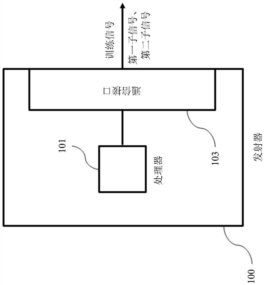
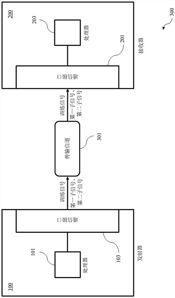
[0043] attached figure 1 Shown is a diagram of a transmitter 100 for multi-carrier communication according to an embodiment. The transmitter 100 includes a processor 101 for generating a training signal S, wherein the training signal S includes a first sub-signal S1 and a second sub-signal S2. The first sub-signal S1 and the second sub-signal S2 are sent continuously in time, and the frequency component of the first sub-signal S1 is frequency-shifted relative to the frequency component of the second sub-signal S2 by a predefined frequency shift amount. The transmitter 100 also comprises a communication interface 103 for sending the training signal S. As shown in FIG.

[0044] The transmitter 100 may be used to perform multi-carrier communication, especially communication based on OFDM, OFDMA, FBMC or SC-FDMA.

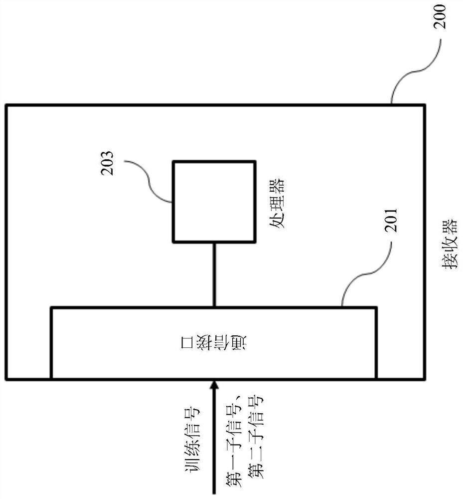
[0045] attached figure 2 Shown is a diagram of a receiver 200 for multi-carrier communication according to an embodiment. The receiver 200 comprises a communicatio...


PUM


Abstract

The invention relates to a transmitter (100) for multi-carrier communication. The transmitter (100) comprises a processor (101) for generating a training signal (S), wherein the training signal (S) comprises a first sub-signal (S1) and a second sub-signal (S2). The first sub-signal (S1) and the second sub-signal (S2) are sent continuously in time, and the frequency component of the first sub-signal (S1) is relative to the frequency of the second sub-signal (S2) The components are frequency shifted by a predefined amount. Said transmitter (100) also comprises a communication interface (103) for sending said training signal (S). The invention also relates to a receiver for performing channel distortion correction, in particular automatic gain control (AGC), based on said received training signal (S).

Description

technical field [0001] The invention relates to the technical field of communication, in particular to training signal generation and channel distortion correction. Background technique [0002] In communication technology, training signals are often used to characterize the transmission channel between a transmitter and a receiver. Typically, the training signal has a predetermined structure and content, which are known at the transmitter and receiver, thereby enabling the receiver to adapt to different characteristics of the transmission channel, such as scattering, fading and power decay with distance. [0003] To accurately represent the characteristics of the transmission channel, the temporal and spectral characteristics of the training signal are crucial. Especially in multi-carrier communication, the communication symbol length and subcarrier frequency spacing for a given total bandwidth are interrelated. For example, an improved representation of the frequency cha...

Claims


Application Information

Patent Timeline
Patent Type & Authority Patents(China)
IPC IPC(8): H04L27/26H04B7/06H03G3/20H03G3/00
CPCH03G3/005H04L27/2601H04L27/2613H03G3/3089H04B7/0617
Inventor 多伦·埃兹里根纳季·特所迪克希米·西隆奥德·里德里
Owner HUAWEI TECH CO LTD
Learn More