

High-rigidity two-plate die locking mechanism
A high-rigidity and clamping technology, applied in the field of two-plate high-rigidity clamping mechanism, can solve the problems of insufficient clamping rigidity and complex control technology, and achieve the effects of low cost, simple technology and high stability
- Summary
- Abstract
- Description
- Claims
- Application Information
AI Technical Summary
Problems solved by technology
Method used
Image

Examples
Embodiment Construction
[0026] The present invention will be further described below in conjunction with the accompanying drawings and specific embodiments.
[0027] refer to Figure 1-4 :
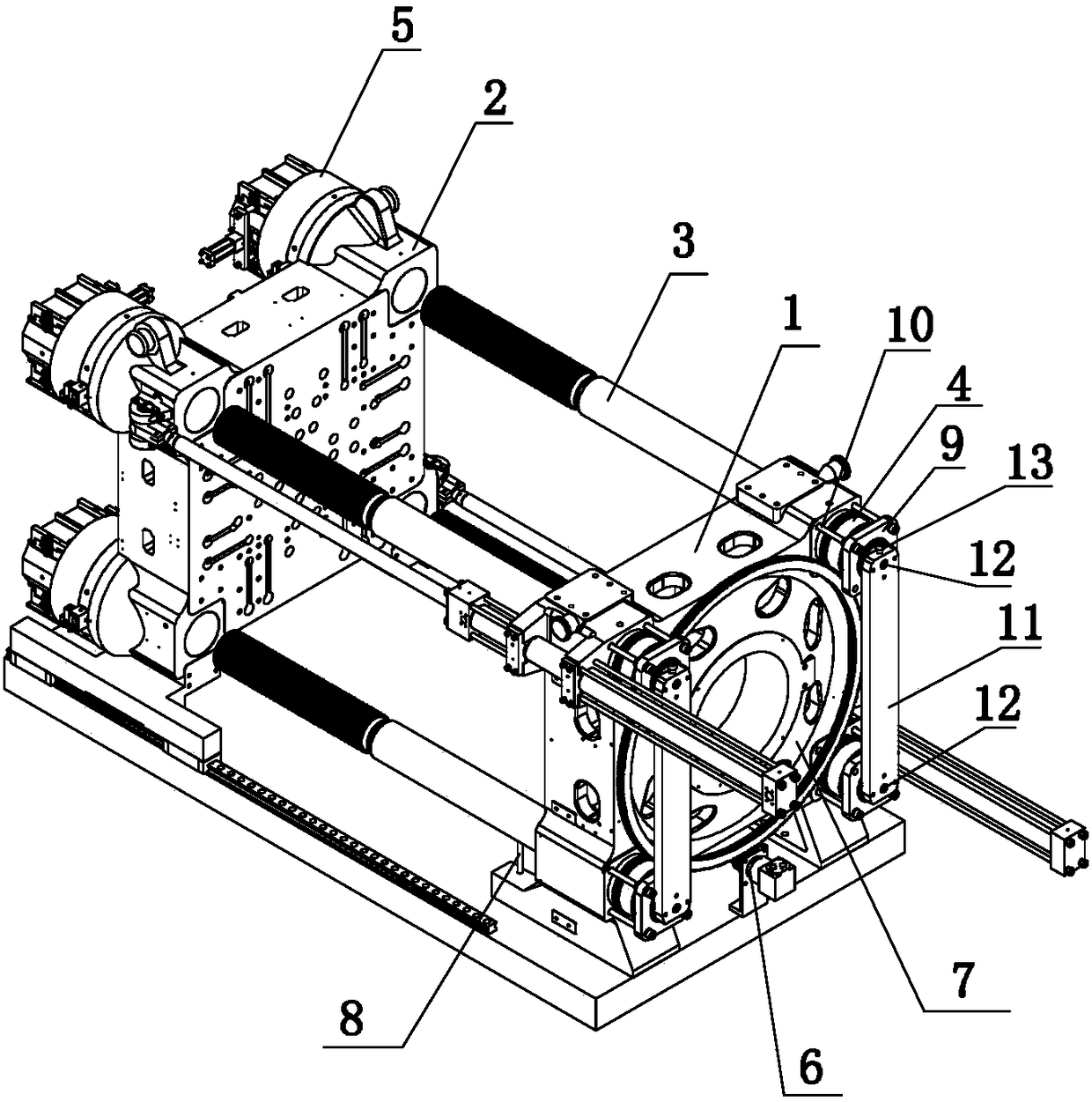
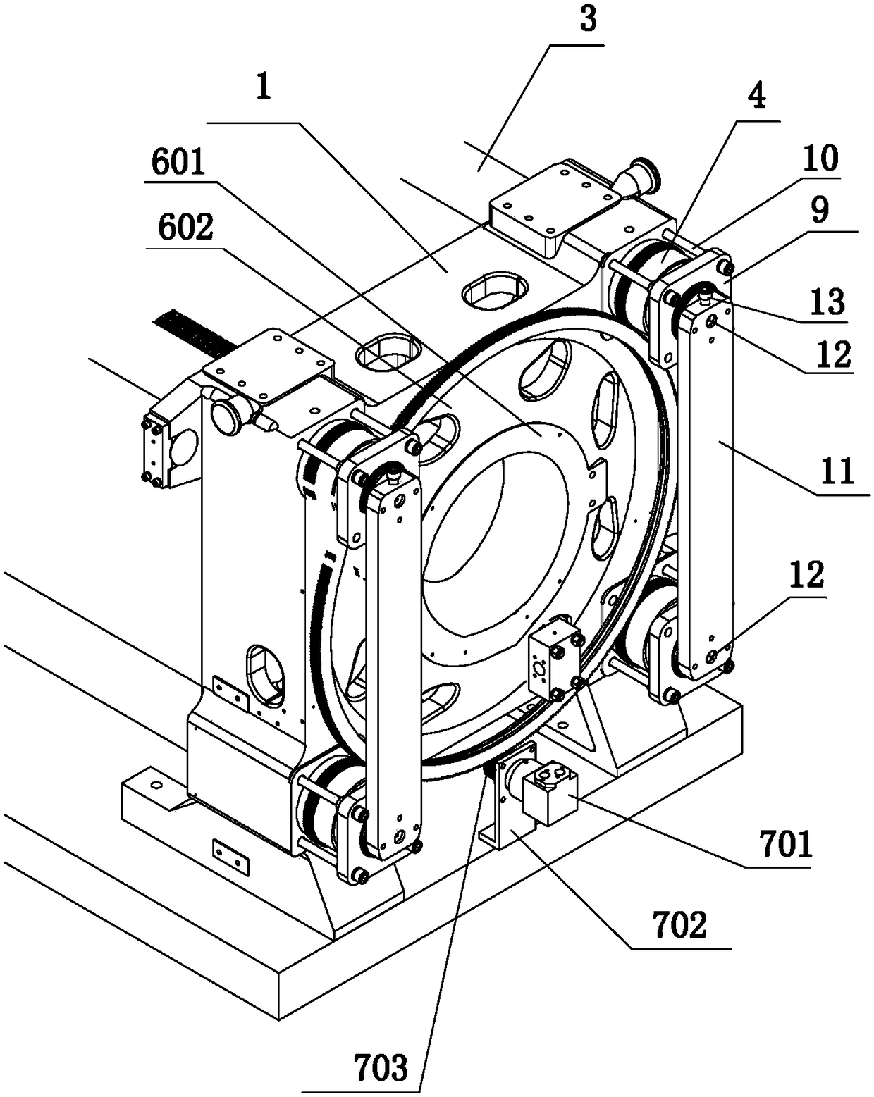
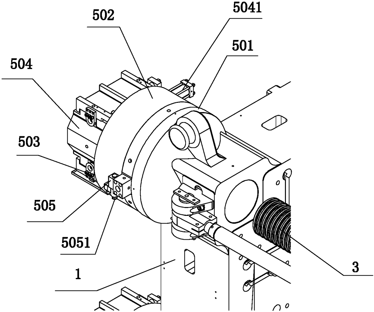
[0028] A high-rigidity mold clamping mechanism includes a fixed template 1, a movable template 2 and four tie rods 3.
[0029] The fixed ends of the four pull rods 3 pass through the four through holes provided at the four corners of the fixed template 1 respectively, and are respectively screwed with the four pull rod nuts 4 to be connected to the fixed template 1 .
[0030] The outer sides of the four pull rod nuts 4 are provided with nut glands 9, and the nut glands 9 are socketed on the corresponding pull rods 3 through the through holes provided on the cover body, and fixed by the connecting rod 10. Installed on the outer end face of the fixed formwork 1.
[0031] The outside of the fixed template 1 is provided with a transmission mechanism 6, the transmission mechanism 6 includes a fixed shaft 601 and a ...
PUM
 Abstract
Description
Claims
Application Information