
Electrocauterization pen special for pyrograph

An electrocautery pen and pyrograph technology, which is applied to the field of painting art creation tools, can solve the problems of troublesome operation, poor grip of the electrocautery pen, unfavorable for painters to paint, etc., so as to reduce the replacement of iron core rods and enhance the hand grip. Sensation, easy to use effect

Pending Publication Date: 2018-07-20
CHINA UNIV OF GEOSCIENCES (WUHAN)
View PDF8 Cites 0 Cited by
  • Summary
  • Abstract
  • Description
  • Claims
  • Application Information

AI Technical Summary

Problems solved by technology

Today, there are many types of ironing pens, but few are suitable for drawing pyrography
The electric soldering pen has a poor grip feeling, the temperature of the soldering iron is not easy to control, there are many types of pen tips, and the operation is troublesome, etc., which are not conducive to the artist's painting

Method used


Image

  • Electrocauterization pen special for pyrograph
  • Electrocauterization pen special for pyrograph
  • Electrocauterization pen special for pyrograph

Examples


Embodiment 1

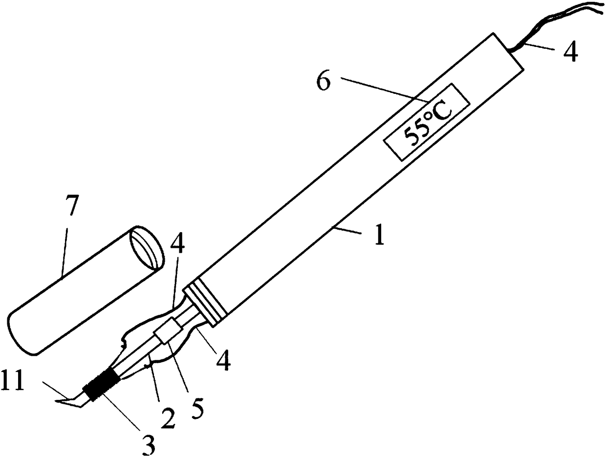
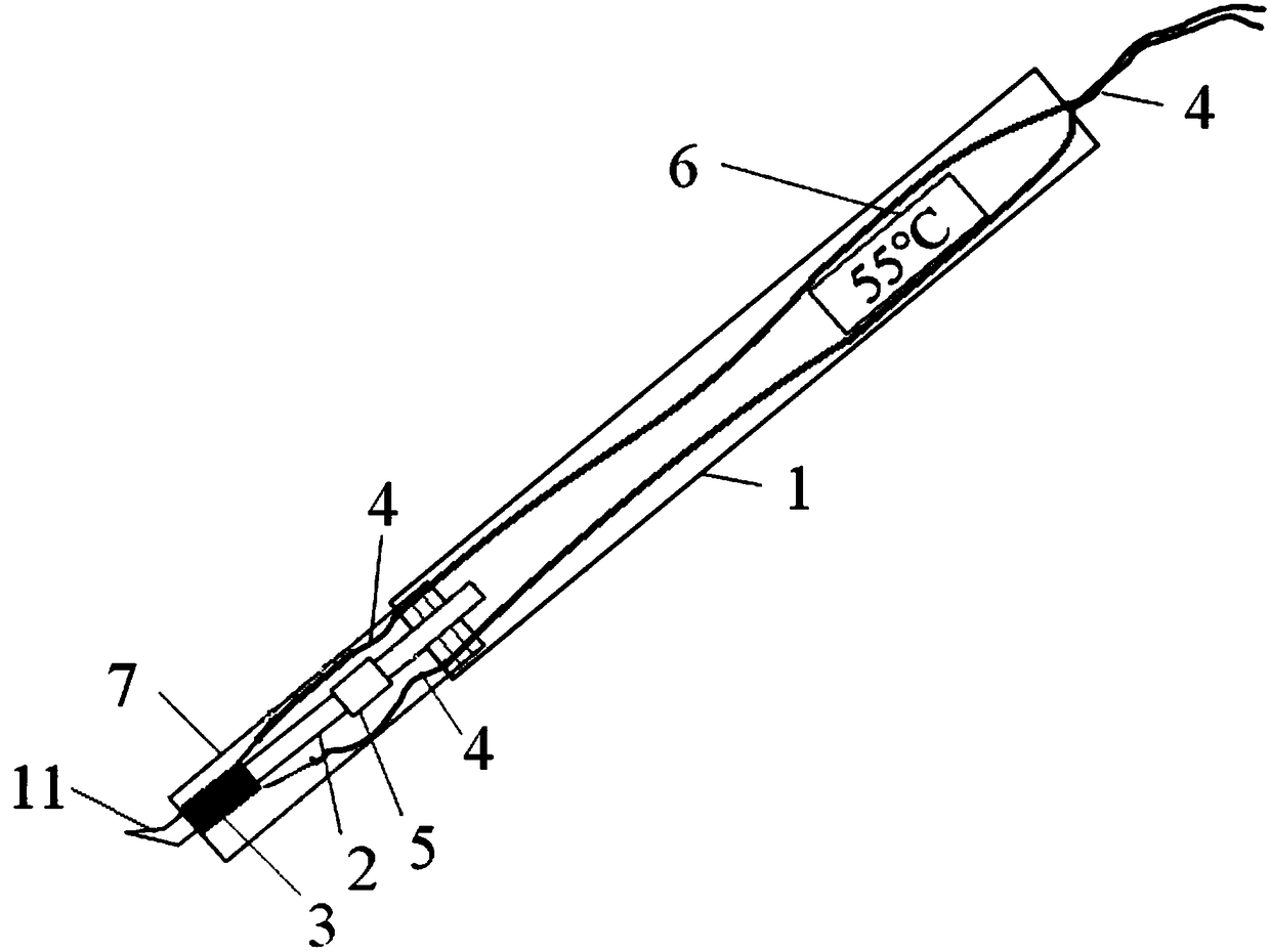
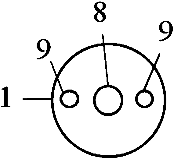
[0025] Such as figure 1 and 2 The schematic diagram of the special electric ironing pen for pyrography shown, the special electric ironing pen for pyrography includes a pen cover 1, the front end of the pen cover 1 is connected with a protective cover 7, preferably, the pen cover 1 and the protective cover 7 are both belts Cylindrical with internal space. The connection methods of the pen case 1 and the protective case 7 include but not limited to welding, pins, threads, etc. Preferably, the pen case 1 and the protective case 7 are connected by threads. The connection between the pen cover 1 and the protective cover 7 is respectively provided with internal and external threads or external and internal threads, that is, the front inner wall of the pen cover 1 is provided with internal threads, and the rear end outer wall of the protective cover 7 is provided with external threads. , by screwing the protective cover 7 into the inner wall of the pen cover 1 to connect the two (...

Embodiment 2

[0030] Such as Figure 5 As shown, the difference between the second embodiment provided by the present invention and the first embodiment lies in the front end of the pen cap 1, the special electric ironing pen in the second embodiment does not have a protective cover 7, but the length of the pen cap 1 is longer than that of the first embodiment. One of the lengths is long, so that one end of the iron core rod 2, the electric furnace wire 3 and the electric wire 4 connected to the electric furnace wire 3 can be included in its internal space, and only the nib 11 of the iron core rod 2 is exposed. That is, the pen tip 11 is located outside the pen case 1, and other structures in the second embodiment are the same as those in the first embodiment.


PUM


Abstract

The invention discloses an electrocauterization pen special for pyrograph. The electrocauterization pen comprises a pen sleeve, a protective sleeve, an iron core rod, an electric stove wire, a power-on wire, a temperature measurer and a display, wherein the protective sleeve and the iron core rod are arranged at the front end of the pen sleeve, the electric stove wire is wound on the iron core rod, the power-on wire is connected with the electric stove wire, the temperature measurer is arranged on the iron core rod, and the display is electrically connected with the temperature measurer. The pen sleeve and the protective sleeve are each in a cylinder shape with an internal space and are connected in an internal and external spiral thread mode. The power-on wire penetrates into the internalspaces of the pen sleeve and the protective sleeve, one end of the power-on wire is connected with the electric stove wire, and the other end of the power-on wire is used for being powered on to heatthe electric stove wire. The iron core rod, the electric stove wire, the temperature measurer and the end, connected with the electric stove wire, of the power-on wire are located in the internal space of the protective sleeve. The electric stove wire emits heat and conducts the heat to the iron core rod, and the temperature measurer is used for measuring the temperature of the iron core rod. Thedisplay is used for displaying the measured temperature of the temperature measurer. The electrocauterization pen is high in hand-holding feeling and easy to use on hand, through visualization, the temperature of the iron core rod is controlled, and unnecessary iron core rod replacement is reduced through the appropriate pen point angle.

Description

technical field [0001] The invention relates to the technical field of painting art creation tools, in particular to a special electric ironing pen for pyrography. Background technique [0002] Pyrography refers to the use of a soldering iron that conducts heat to a certain extent to iron out rich-layered paintings on silk or templates. The unique painting method makes it unique in the art of painting. Since the development of pyrography, its painting work has also evolved from the previous fire to the electric pen. Today, there are many types of ironing pens, but few are suitable for drawing pyrography. The electric soldering pen has a poor grip feeling, the temperature of the soldering iron is not easy to control, there are many types of pen tips, and the operation is troublesome, etc., which are not conducive to the painter's painting. [0003] Therefore, in view of the above-mentioned problems of the prior art, it is indeed necessary to design a pyrography electric cau...

Claims


Application Information

Patent Timeline
Patent Type & Authority Applications(China)
IPC IPC(8): B44B7/00B44C1/02
CPCB44B7/00B44C1/02
Inventor 李其胜刘子源
Owner CHINA UNIV OF GEOSCIENCES (WUHAN)
Learn More