Bottom limiting ball valve

A technology of limit balls and valve balls, which is applied in the direction of multi-way valves, valve devices, cocks including cut-off devices, etc., can solve the problems of high aesthetic requirements, affecting the limit position, and easy corrosion of iron handles, etc., and achieve structural The design is simple and flexible, the limit structure is simple, and the limit is flexible.

Active Publication Date: 2018-07-20
TAIZHOU BANCHENG HVAC TECH CO LTD
View PDF11 Cites 4 Cited by
  • Summary
  • Abstract
  • Description
  • Claims
  • Application Information

AI Technical Summary

Problems solved by technology

For example, in the case of surface installation, the protruding limit structure is poor in aesthetics, and the iron handle is easy to corrode and affect the limit position. The convex limit structure is simple but heavy, and the inner limit structure is light in weight but the process is complicated.
[0005] Top-entry ball valves are generally used for surface-mounted applications, like bathroom faucets, which require high aesthetics, and the limiting structure outside the valve body is poor in aesthetics, and some structures have patent barriers

Method used


Image

  • Bottom limiting ball valve
  • Bottom limiting ball valve
  • Bottom limiting ball valve

Examples


Embodiment Construction

[0023] The present invention will be further described below in conjunction with preferred embodiments.

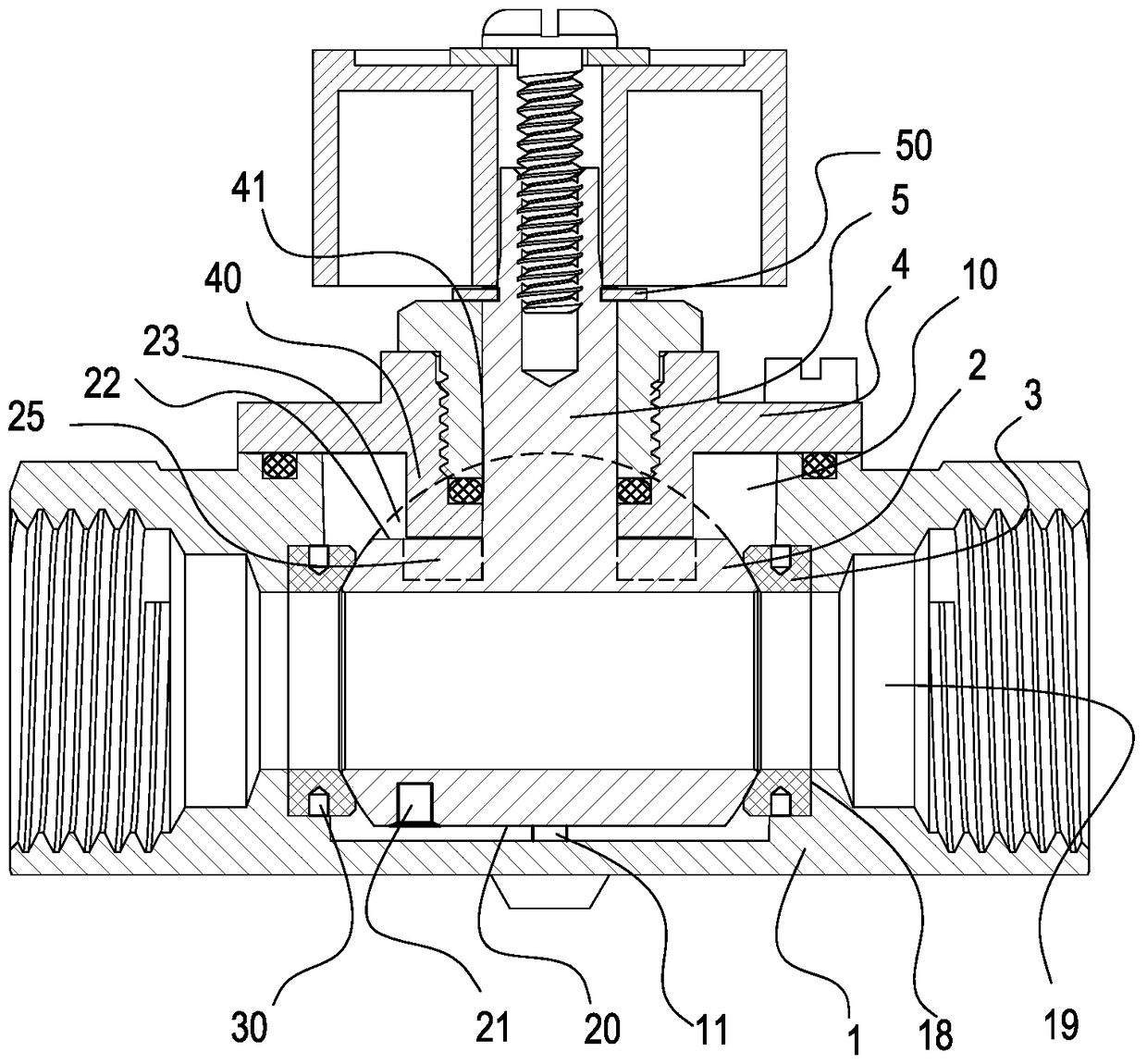
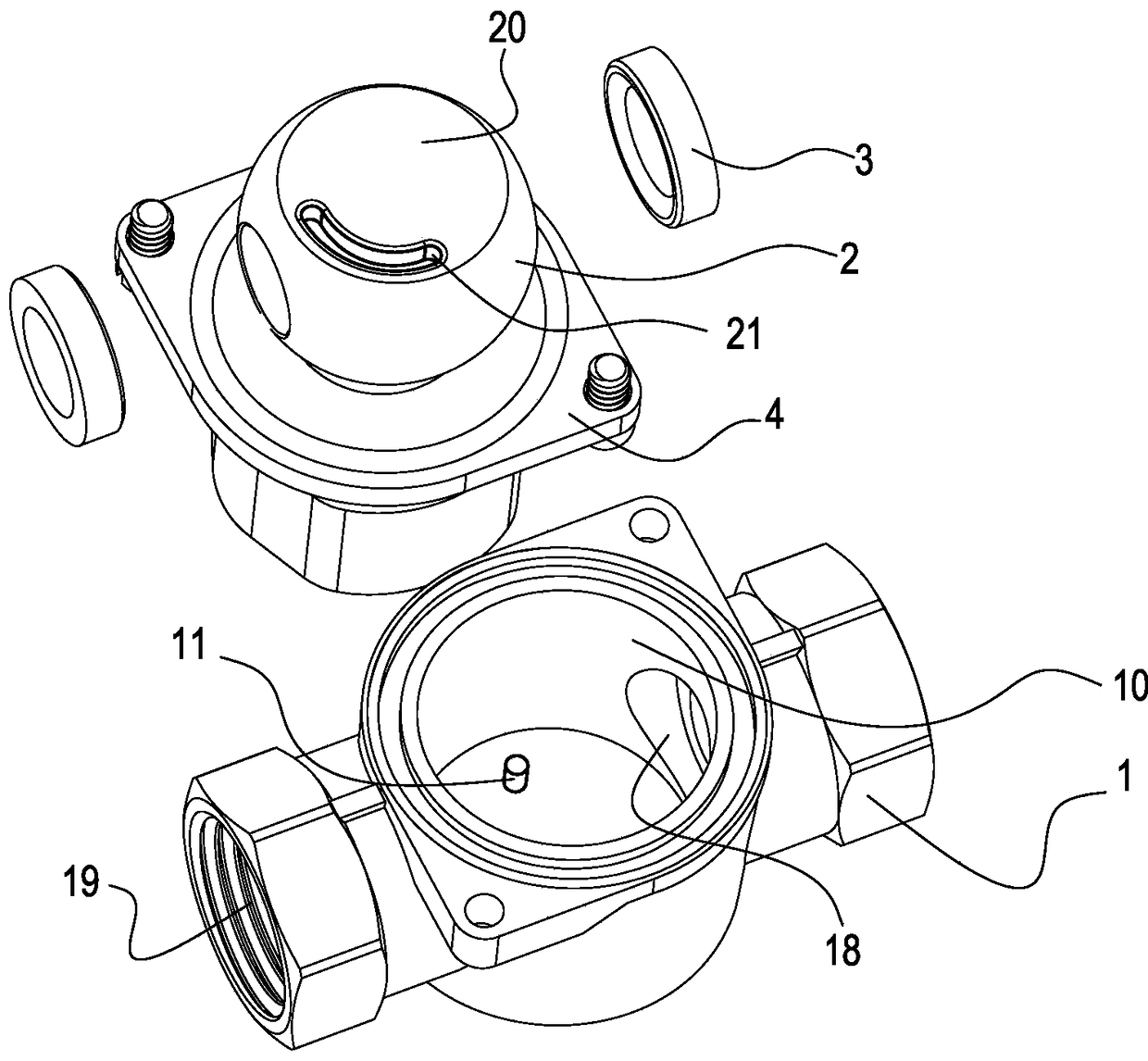
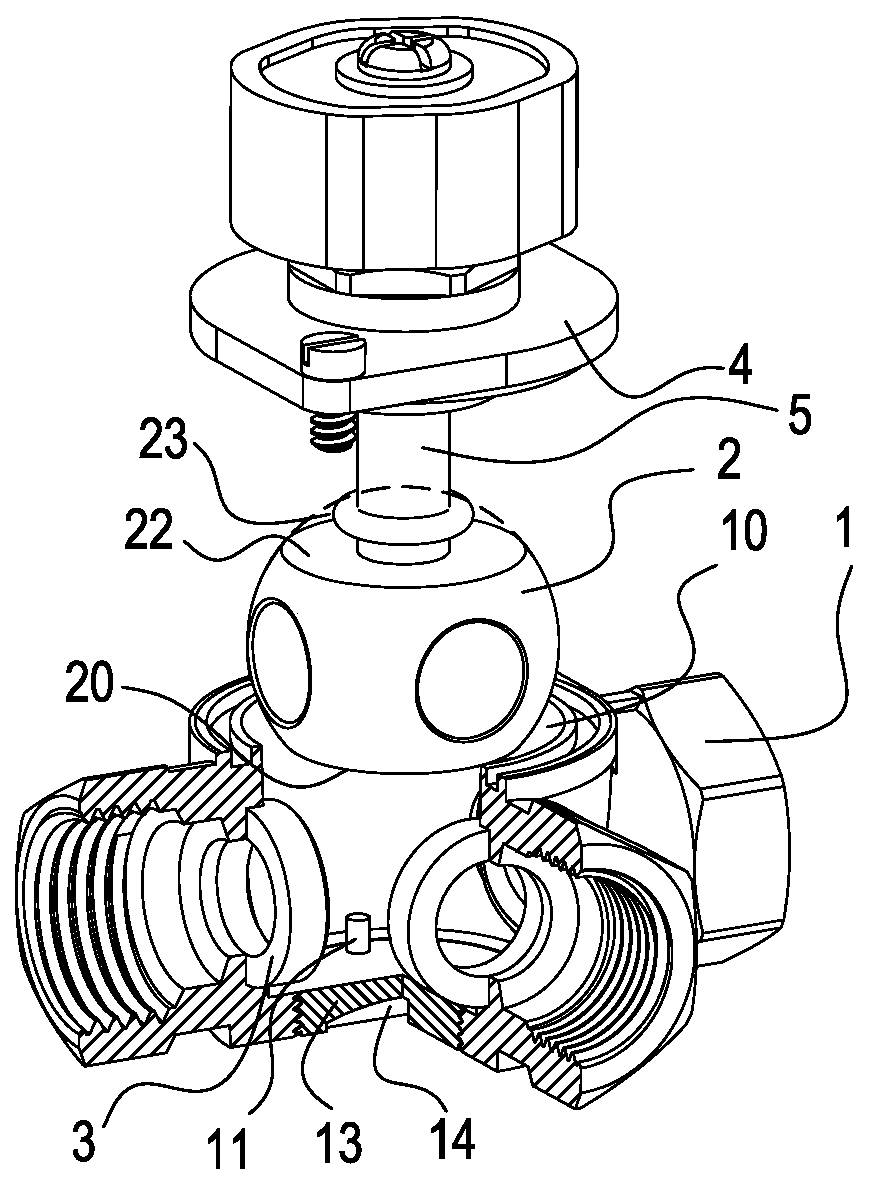
[0024] Such as figure 1 with figure 2 As shown, a bottom limit ball valve includes a valve body 1, a valve ball cavity 10 with an open upper end of the valve body 1, a valve ball 2 placed in the valve ball cavity 10, and a valve body 1 in contact with the valve ball. 2 and the sealing ring 3 that realizes the limit and sealing, the valve ball 2 and the sealing ring 3 are loaded from the upper part of the valve ball cavity 10, and the center position of the valve ball 2 is limited by the valve cover 4; The convex pin part 11, the convex pin part 11 is located at the non-axis position of the valve ball cavity 10; the bottom of the valve ball 2 is a first plane part 20, and the first plane part 20 has a non-circular concave arc groove 21 ; the protruding pin part 11 is positioned in the concave arc groove 21 to limit the rotation angle of the valve ball 2 .

[0025] The v...


PUM


Abstract

The invention relates to a ball valve. The bottom limiting ball valve comprises a valve body, an open valve ball cavity in the upper end of the valve body, a valve ball arranged on the valve ball cavity and a sealing ring for being in contact with the valve body and the valve ball to realize limiting and sealing. The valve ball and the sealing ring are arranged from the upper portion of the valveball cavity, and the center position of the valve ball is limited through a valve cover. A convex pin part is arranged at the bottom of the valve body, and the convex pin part is positioned at the non-axial position of the valve ball cavity. According to the bottom limiting ball valve, the novel inner limiting structure is provided for an upper-mounted ball valve, the structure is not limited by an outer structure of the valve body, the appearance design is more concise, and the bottom limiting ball valve is more suitable for open-mounted occasions, flexible in limiting and accurate in positioning and has the uniqueness and competitiveness of a market structure.

Description

technical field [0001] The invention relates to a ball valve. Background technique [0002] Valve products are widely used in water conservancy, construction, transportation and other fields, accounting for about 5% of the output value of the entire machinery industry, among which ball valves are the most common type of valve. The ball valve realizes the circulation and cut-off of the medium connected to the pipeline through the rotation of the valve ball. The structure of the ball valve rotation limit is one of the keys to ensure the normal operation of the valve. Inaccurate limit will cause the pipeline to be closed, not in place, and the flow resistance is large. noise etc. [0003] The ball valve limit structure in the prior art is "a valve ball limit structure" published by the publication number CN 102359616 A. The ball valve realizes the valve ball through the limit plane on the valve stem 3 and the limit structure of the middle hole of the valve body 1. rotation li...

Claims


Application Information

Patent Timeline
Patent Type & Authority Applications(China)
IPC IPC(8): F16K11/087F16K5/20
CPCF16K5/0605F16K5/0689F16K11/0873
Inventor 黄晓峰
Owner TAIZHOU BANCHENG HVAC TECH CO LTD
Why Eureka
Try Eureka