Unlock instant, AI-driven research and patent intelligence for your innovation.

Aircraft flutter analysis network model Laguerre modeling method

A grid model and flutter analysis technology, applied in the aerospace and information fields, can solve problems such as complex flutter models

Active Publication Date: 2018-07-20
XIAN FEISIDA AUTOMATION ENG
View PDF5 Cites 1 Cited by
  • Summary
  • Abstract
  • Description
  • Claims
  • Application Information

AI Technical Summary

Problems solved by technology

[0006] In order to overcome the problem that the existing technology cannot effectively express the complex flutter model under the influence of aerodynamic force and strength changes, the present invention provides a Laguerre modeling method for the grid model of aircraft flutter analysis. Multiple grid points, under the influence of aerodynamic and strength changes such as different flight speeds, atmospheric densities, airflow environments, and different temperatures, the complex flutter grid model is represented according to the body shaft system decomposition method, and the installation of sensors is proposed according to the requirements of the model. According to the data and image recording requirements, the data is obtained through effective flutter flight tests, the excitation function is obtained through the measurement value of the airflow sensor, the vibration variable is approximated and equivalently described by the Laguerre function, and the coordinates of the body axis system are determined according to the identification method Solve the three axial vibration equations at the grid points, which solves the technical problem that the existing technology cannot effectively express the complex flutter model under the influence of aerodynamic force and strength changes

Method used


Image

  • Aircraft flutter analysis network model Laguerre modeling method
  • Aircraft flutter analysis network model Laguerre modeling method
  • Aircraft flutter analysis network model Laguerre modeling method

Examples


Embodiment Construction

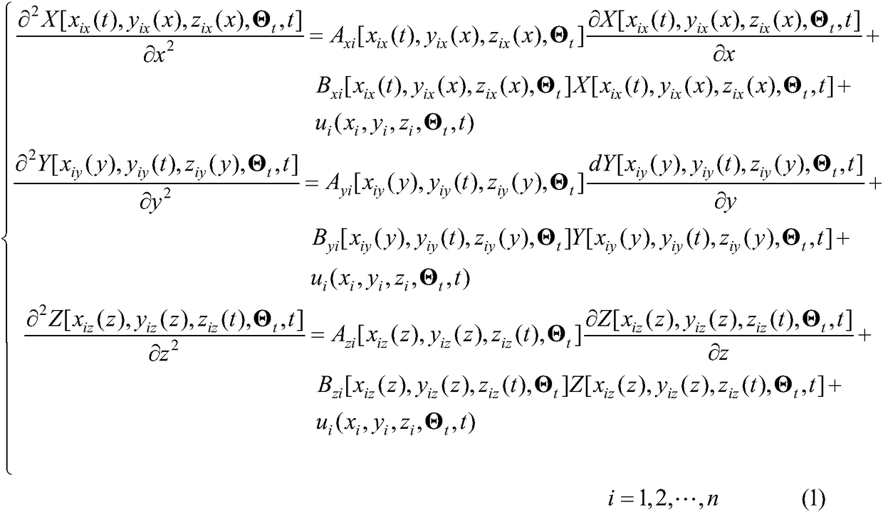
[0063] Step 1: Analyze the complex flutter model with the aircraft body shaft system OXYZ, and select n grid points in the body shaft system: x i ,y i ,z i , i=1,2,...,n, when vibrating, the dynamic three-axis position components x(y,z,t),y(x,z,t),z(x,y,t) of grid points are time t and other two-axis position functions, for the convenience of expression, x ix (y, z, t) as an example, the subscript i=1, 2,..., n is the grid point label, the second letter x, y, z of the subscript respectively represent the three axes of vibration in the body axis system OXYZ component, in order to simplify the problem, when considering the i=1,2,...,n grid points vibrating in the x-axis direction, x(y,z,t)=x ix (t),y(x,z,t)=y ix (x),z(x,y,t)=z ix (x), when considering the i=1,2,...,n grid points vibrating in the y-axis direction, x(y,z,t)=x iy (y),y(x,z,t)=y iy (t),z(x,y,t)=z iy (y), when considering the i=1,2,...,n grid points vibrating in the z-axis direction, x(y,z,t)=x iz (z),y(x,z,...


PUM


Abstract

To overcome the problem of a complex flutter model under influence of aerodynamic force and intensity change cannot be effectively expressed in the prior art, the invention provides an aircraft flutter analysis network model Laguerre modeling method. According to the method, a plurality of grid points are selected in aircraft body shafting, a complex flutter network model ix expressed according toa body shafting decomposition method under influence of aerodynamic force and intensity change of different flight speeds, atmosphere density, airflow environment and different temperatures, requirements of installing a sensor and recording data and images are proposed according to a requirement of establishing the model, data are obtained through an effective flutter flight test, an excitation function is obtained through a measured value of an airflow sensor, a Laguerre function is adopted to perform approximate and equivalent description of a vibration variable, solving of three axial vibration equations at the body shafting coordinate grid points is determined according to an identification method at the same time, and the technical problem that a complex flutter model under influenceof aerodynamic force and intensity change cannot be effectively expressed in the prior art.

Description

technical field [0001] The invention relates to a ground comprehensive test method for flight safety of aircraft such as civil aircraft, fighter jets, and unmanned aerial vehicles, in particular to a Laguerre modeling method for flutter analysis grid models of aircraft, and belongs to the field of aerospace and information technology. Background technique [0002] Flutter is a large-amplitude vibration phenomenon that occurs when an elastic structure is coupled by aerodynamic, elastic, and inertial forces in a uniform airflow. For aircraft, vibration occurs after an uncertain disturbance in flight. At this time, due to the effect of the airflow, the elastic structure of the aircraft such as the wing, empennage or control surface will generate additional aerodynamic force; as an exciting force, the additional aerodynamic force will aggravate the vibration of the structure. At the same time, the damping force of the air on the aircraft structure tries to weaken the vibration;...

Claims


Application Information

Patent Timeline
IPC IPC(8): G05B13/04
CPCG05B13/042
Inventor 史忠科
Owner XIAN FEISIDA AUTOMATION ENG