Centralized control system of security monitoring equipment

A centralized control system and security monitoring technology, applied in closed-circuit television systems, TV system components, anti-theft alarm mechanical start-up, etc., can solve the problems of irresponsible residents, lack of security monitoring, weak monitoring, etc., to achieve Guarantee the safety of life and property, ensure that there are no dead ends in monitoring, and delay the effect of intrusion time

Inactive Publication Date: 2018-07-20
吴君国
View PDF7 Cites 2 Cited by
  • Summary
  • Abstract
  • Description
  • Claims
  • Application Information

AI Technical Summary

Problems solved by technology

[0002] With the development of society, people's spiritual wealth and material wealth are increasing day by day, and people also pay special attention to the safety of themselves and their property. Property companies need to invest relatively more manpower and material resources in community property management and protection of residents' lives and property safety. , in the current community security, a security guard is usually placed at the entrance of the community to supervise the people coming and going. Without the function of security monitoring, especially at night, the monitoring is weaker, and it is impossible to establish real-time communication between property management personnel and residents, which is not conducive to ensuring the personal and property safety of residents. The lack of strict monitoring during the day will lead to criminals entering Residential areas lead to irreversible consequences. It is necessary to provide a security monitoring system that establishes real-time communication with residents, strictly controls the entrance of residential areas, and prevents criminals from entering.

Method used


Image

  • Centralized control system of security monitoring equipment

Examples


Embodiment Construction

[0023] The present invention will be further described in detail below in conjunction with the accompanying drawings, so that those skilled in the art can implement it with reference to the description.

[0024] It should be understood that terms such as "having", "comprising" and "including" used herein do not exclude the presence or addition of one or more other elements or combinations thereof.

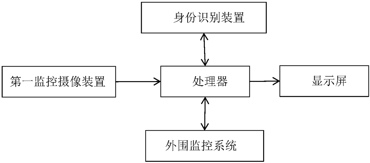
[0025] Such as figure 1 As shown, the present invention provides a centralized control system for security monitoring equipment, including:

[0026] A main monitoring system, which is set in the monitoring room, and the main monitoring system includes a processor connected to the processor and a display screen;

[0027] The processor includes a resident data storage and an information comparison module, the resident data storage is divided into corresponding independent storage spaces according to the household addresses of the households, and each of the independent storage space...


PUM


Abstract

The invention discloses a centralized control system of security monitoring equipment. The centralized control system comprises a main monitoring system, an identification device, auxiliary monitoringsystems and a periphery monitoring system, wherein the main monitoring system comprises a processor and a display connected with the processor, the processor comprises a inhabitant data memory and aninformation comparison module, and the information comparison module calls information in the inhabitant data memory for data comparison; the identification device comprises a camera device and an operation panel, a user presses the number of the corresponding house address on the operation panel and presses a shooting key for shooting, information is transmitted to the information comparison module, the information comparison module calls information in isolated storage space for data comparison with a received photo, and a comparison result is given; the periphery monitoring system comprises an electronic fence and vertical poles arranged on the inner side of the electronic fence, the electronic fence is arranged at the edge of the outermost side of an inhabitation zone to enclose the inhabitation zone, and monitoring devices are arranged at the upper ends of the vertical poles. The centralized control system of security monitoring equipment completely eradicates hidden danger of entry of law breakers, meanwhile, entry of visitors allowed by inhabitants is not affected, and safety of the inhabitant zone is guaranteed.

Description

technical field [0001] The invention relates to the security field, in particular to a centralized control system for security monitoring equipment. Background technique [0002] With the development of society, people's spiritual wealth and material wealth are increasing day by day, and people also pay special attention to the safety of themselves and their property. Property companies need to invest relatively more manpower and material resources in community property management and protection of residents' lives and property safety. , in the current community security, a security guard is usually placed at the entrance of the community to supervise the people coming and going. Without the function of security monitoring, especially at night, the monitoring is weaker, and it is impossible to establish real-time communication between property management personnel and residents, which is not conducive to ensuring the personal and property safety of residents. The lack of str...

Claims


Application Information

Patent Timeline
IPC IPC(8): G07C9/00G08B13/02G08B13/19H04N5/225H04N7/18H04W4/02
CPCH04N7/18H04W4/021G08B13/02G08B13/19G07C9/38G07C9/37H04N23/56
Inventor 吴君国
Owner 吴君国
Why Eureka
Try Eureka