Injection pump

A syringe pump and syringe technology, applied in the field of microfluidics, can solve the problems of poor control accuracy, complex structure, long assembly time, etc., and achieve the effect of improving stability

Inactive Publication Date: 2018-07-24
SUZHOU XUNFEI SCI INSTR CO LTD
View PDF7 Cites 4 Cited by
  • Summary
  • Abstract
  • Description
  • Claims
  • Application Information

AI Technical Summary

Problems solved by technology

[0003] The drive of the fluid in the channel of the microfluidic chip is generally realized by a syringe pump. The syringe pump in the prior art has the problems of poor control accuracy, many parts, complex structure, and long assembly time.

Method used


Image

  • Injection pump
  • Injection pump
  • Injection pump

Examples


Embodiment Construction

[0023] The technical solutions of the present invention will be clearly and completely described below in conjunction with the accompanying drawings. Apparently, the described embodiments are some of the embodiments of the present invention, but not all of them. Based on the embodiments of the present invention, all other embodiments obtained by persons of ordinary skill in the art without making creative efforts belong to the protection scope of the present invention.

[0024] In the description of the present invention, it should be noted that the terms "center", "upper", "lower", "left", "right", "vertical", "horizontal", "inner", "outer" etc. The indicated orientation or positional relationship is based on the orientation or positional relationship shown in the drawings, and is only for the convenience of describing the present invention and simplifying the description, rather than indicating or implying that the referred device or element must have a specific orientation, ...


PUM


Abstract

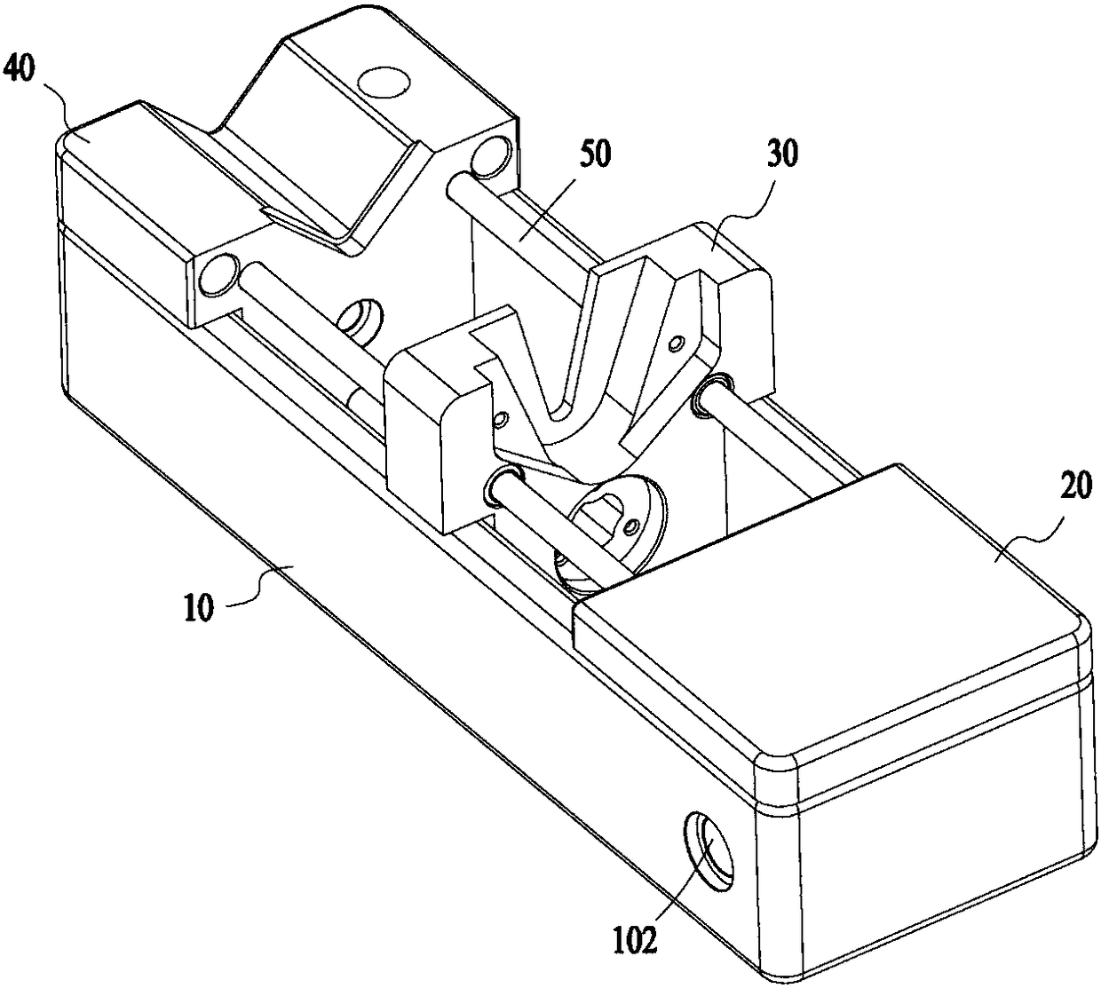
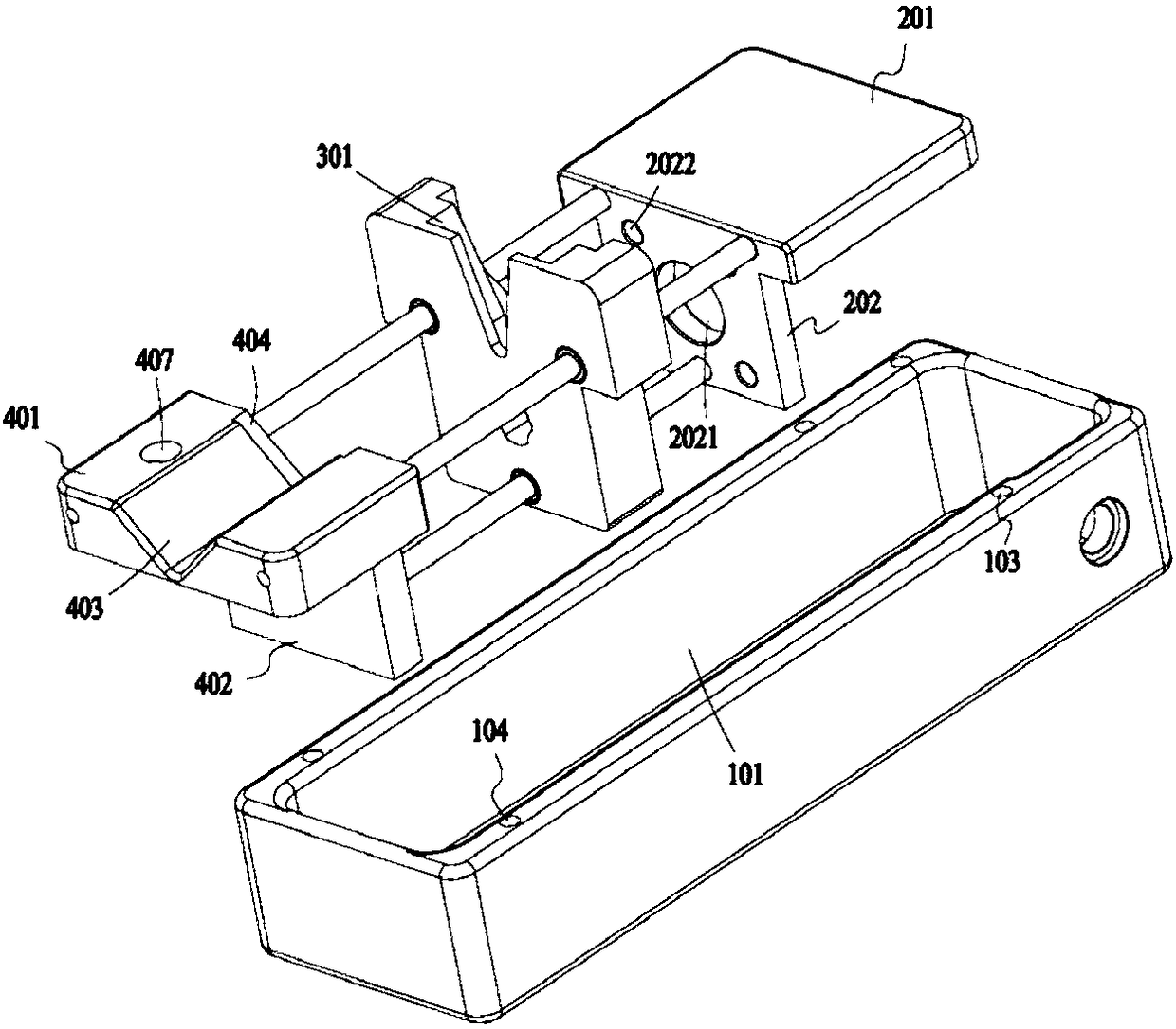
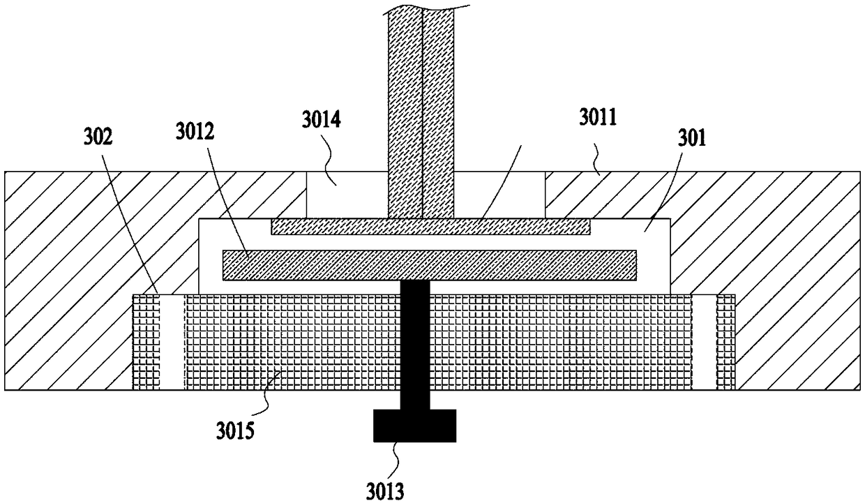
The invention discloses an injection pump. The injection pump comprises a motor, a sliding block and a cylinder base; the motor acts on the sliding block to drive the sliding block to be close to or far away from the cylinder base; a first clamping groove for limiting an injector pull rod cap is formed in the sliding block; a second clamping groove for limiting an injector needle cylinder cap is formed in the cylinder base; the first clamping groove comprises a baffle and a driving plate which are arranged opposite; the driving plate is connected with a driving piece; and the driving piece acts on the driving plate and can drive the driving plate to be close to or far away from the baffle. The pull rod cap of the injector is limited between the baffle and the driving plate and the pull rodcap can be extruded in the first clamping groove through motion of the driving plate, so that relative fixation of the pull rod cap and the sliding block is realized and the stability in the injection process is improved.

Description

technical field [0001] The present application relates to the field of microfluidic technology, in particular to a syringe pump. Background technique [0002] Microfluidic chip (microfluidic chip) has become an important platform for microanalysis research in the fields of biology and chemistry in recent years because of its advantages of low consumption, rapidity, and integration of various analysis functions. Since microfluidic chip analysis is carried out in a micron-scale separation and analysis channel with network characteristics on a chip of a few square centimeters, the sample preparation and injection involved in biochemical experiments can be realized through the rapid manipulation of nanoliter or even picoliter sample scale. , mixing, reaction, separation, detection and other operations of an invention analysis technology. [0003] The drive of the fluid in the channel of the microfluidic chip is generally realized by a syringe pump. The syringe pump in the prior...

Claims


Application Information

Patent Timeline
Patent Type & Authority Applications(China)
IPC IPC(8): B01L3/00
CPCB01L3/50273B01L2400/0475
Inventor 张宝芳朱凯旋马剑
Owner SUZHOU XUNFEI SCI INSTR CO LTD
Why Eureka
Try Eureka