
Ring workpiece marking device

A ring-shaped workpiece and a ring-shaped technology, applied in the field of ring-shaped workpiece marking devices, can solve the problems of ring-shaped connecting piece vibration, different distances, and blurred markings.

Inactive Publication Date: 2019-08-06
SHANDONG TAIKAI PRECISION CASTING
View PDF9 Cites 1 Cited by
  • Summary
  • Abstract
  • Description
  • Claims
  • Application Information

AI Technical Summary

Problems solved by technology

[0004] But the above-mentioned device is only suitable for the marking of the ring connectors of the same thickness. When the ring connectors of different thicknesses are placed on the rotating disk, since the two marking heads are fixed, the marking head positioned below and the ring The distance between the lower surface of the connector remains constant, while the distance between the upper printing head and the upper surface of the circular connector changes, resulting in different distances between the two printing heads and the end face of the circular connector, resulting in two The two printing heads do not reach the surface of the annular connector at the same time. When one of the printing heads reaches the surface of the annular connector first, it will cause the ring connector to vibrate. When the other printing head reaches the surface of the annular connector When printing the label, the printed label will be blurred, which will affect the quality of the printed label

Method used


Image

  • Ring workpiece marking device
  • Ring workpiece marking device

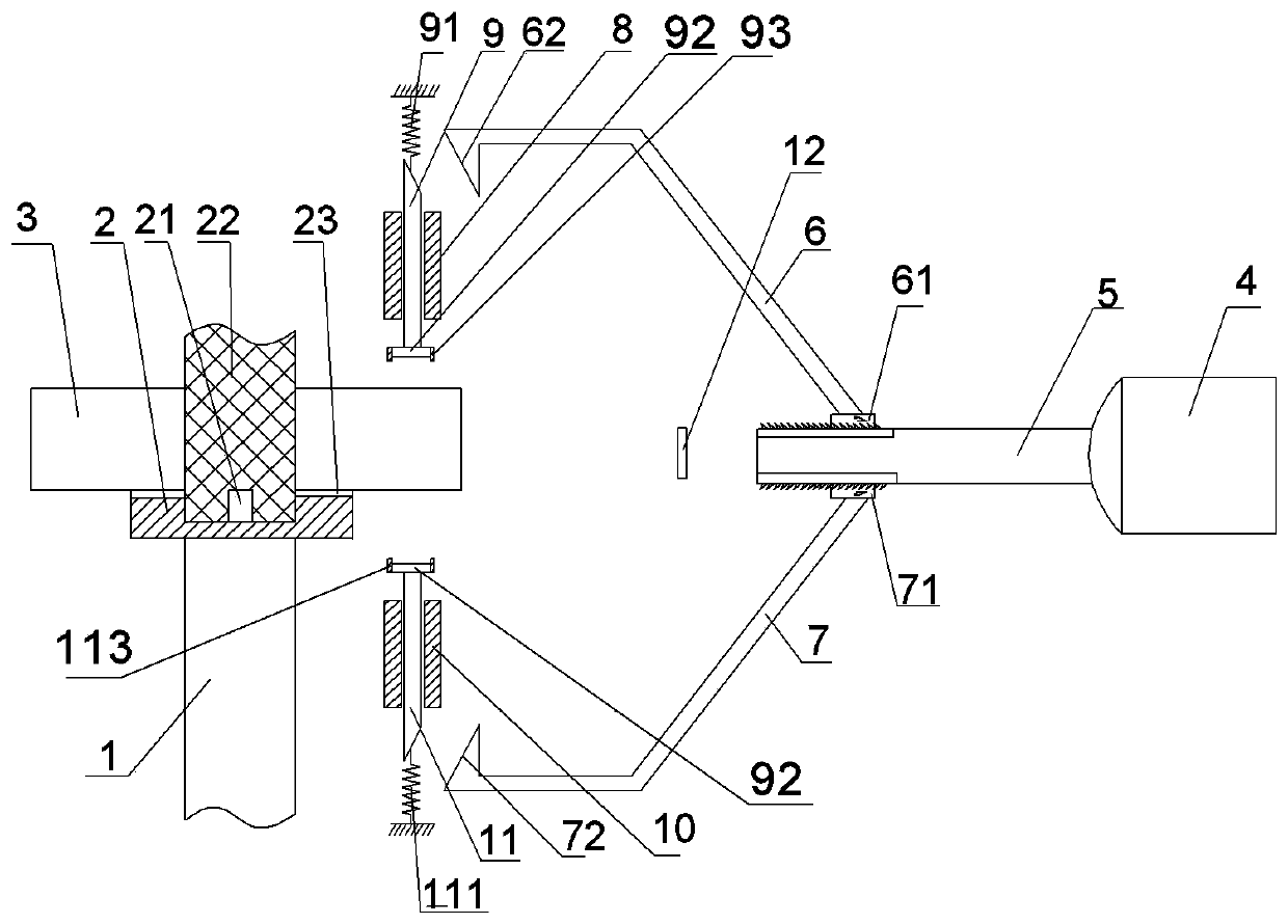
Examples


Embodiment Construction

[0022] Further detailed explanation through specific implementation mode below:

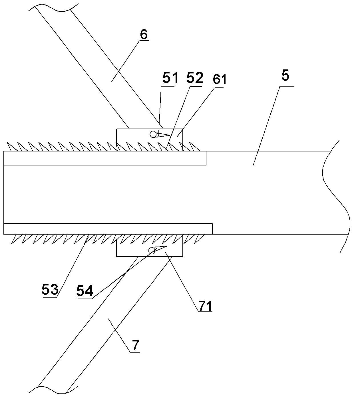
[0023] The reference signs in the drawings of the description include: fixed disk 2, bayonet pin 21, positioning column 22, electromagnet disk 23, ring connector 3, linear motor 4, connecting rod 5, first pawl 51, first ratchet 52 , the second ratchet 53, the second pawl 54, the first curved rod 6, the first electromagnet 61, the first slope 62, the second curved rod 7, the second electromagnet 71, the second slope 72, the first One chute 8, the first wedge bar 9, the first return spring 91, the printing head 92, the first annular pressing member 93, the second chute 10, the second wedge bar 11, the second return spring 111, the second Annular pressing part 113, marking switch 12.

[0024] Such as figure 1 As shown, the ring-shaped workpiece marking device of this embodiment includes a frame, and the frame is provided with a fixing mechanism and a marking mechanism.

[0025] The fixing mechani...


PUM


Abstract

The invention belongs to the automobile parts manufacturing field and discloses a mark printing device for annular workpieces. The mark printing device comprises a rack; the rack is provided with a fixing mechanism and a mark printing mechanism; the fixing mechanism comprises a fixing disk; the mark printing mechanism is located to one side of the fixing disk and comprises a connection rod; an upper magnetic member is attached to the upper surface of the connection rod; a lower magnetic member is attached to the lower surface of the connection rod; a first electromagnet is slidably connected onto the upper magnetic member; a second electromagnet is slidably connected onto the lower magnetic member; the first electromagnet is fixedly connected with a first curved rod; the second electromagnet is fixedly connected with a second curved rod; the free end of the first curved rod is provided with a first inclined surface; the free end of the second curved rod is provided with a second inclined surface; a first wedge bar is connected with a first annular switch; a second wedge bar is connected with a second annular switch; and the inner sides of the first annular switch and the second annular switch are both provided with mark printing heads. According to the mark printing device for the annular workpieces of the invention, the problem that printed marks on the upper end surface and lower end surface of an annular connecting member are blurred caused by the difference of the thickness of the annular connecting member can be solved.

Description

technical field [0001] The invention relates to the field of auto parts manufacturing, in particular to a ring-shaped workpiece marking device. Background technique [0002] Automotive ring connectors are usually made of iron materials and are generally used to connect two parts. After the ring connector is processed, it is usually necessary to print some marks on both ends of the connector, such as the production label and the like. There are usually two existing processing methods. One is to use manual marking, that is, after marking one end of the connecting piece through the marking machine, manually turn the connecting piece over, and then use the marking machine to mark the other end of the connecting piece. Printing on one end face is complex and labor-intensive; the other is to use numerical control equipment to control the movement of the marking machine to print on both ends of the connector, but this type of equipment is usually expensive, and for small The cost...

Claims


Application Information

Patent Timeline
Patent Type & Authority Patents(China)
IPC IPC(8): B41J3/413
CPCB41J3/413
Inventor 车臣飞
Owner SHANDONG TAIKAI PRECISION CASTING
Learn More