High strength prying-resistant door

An anti-pry door, high-strength technology, applied in the field of anti-pry doors, can solve the problem that the door is easy to be pryed open by unlawful personnel, and the property and life safety of users cannot be well guaranteed, and achieves suitable promotion, simple structure, and convenient operation. Effect

Pending Publication Date: 2018-07-24
河南大红门门业有限公司
View PDF0 Cites 1 Cited by
  • Summary
  • Abstract
  • Description
  • Claims
  • Application Information

AI Technical Summary

Problems solved by technology

[0002] A door refers to the entrance and exit of a building or a device installed at the entrance and exit that can be opened and closed. A door is an entity that divides a limited space. Its function is to connect and close the entrances and exits of two or more spaces. The entrance door is also called a security door. , Most houses are installed with entry doors when they are completed. Some consumers will replace them for safety and other considerations. The entry doors mainly include pure steel entry doors and armored doors. Armored doors are high-end entry doors. The main feature of the door is that it does not use the traditional surface treatment method, but adds a layer of wood veneer on the surface of the steel entrance door, which not only ensures the safety elements of the entrance door, but also greatly improves the grade of the door. , It can also be better coordinated with the interior decoration. Compared with the entrance door, consumers use more interior doors. There are many types of interior doors, and they are also the most confusing varieties for consumers. But now The door is easy to be opened by illegal personnel, and the property and life safety of the user cannot be well guaranteed. Therefore, we have proposed a high-strength anti-pry door to solve the above problems

Method used


Image

  • High strength prying-resistant door
  • High strength prying-resistant door
  • High strength prying-resistant door

Examples


Embodiment Construction

[0016] The following will clearly and completely describe the technical solutions in the embodiments of the present invention with reference to the accompanying drawings in the embodiments of the present invention. Obviously, the described embodiments are only some, not all, embodiments of the present invention.

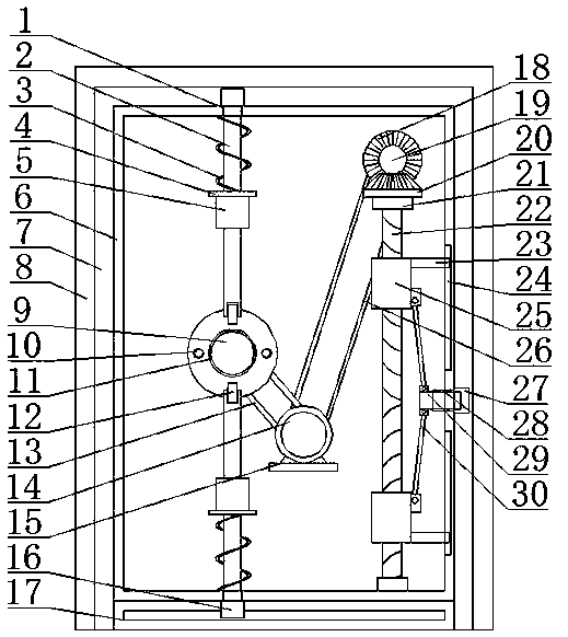
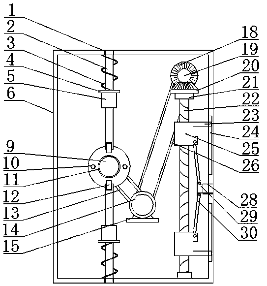
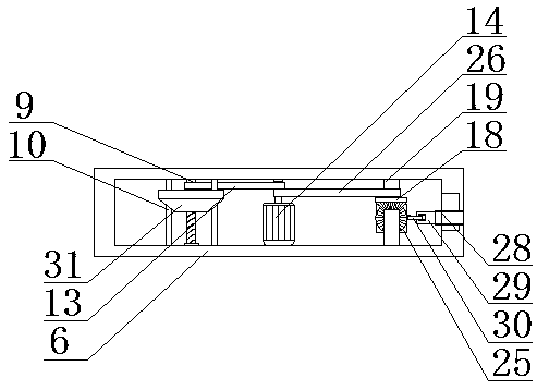
[0017] refer to Figure 1-3 , a high-strength tamper-resistant door, including a door frame 7, the door frame 7 is provided with a groove for easy installation, the lower end of the opposite side of the door frame 7 is jointly fixed with a connecting rod 17, and the connecting rod 17 and the door frame 7 are opposite to each other. One side is provided with placement groove 16, is convenient to fix, and the other side of doorframe 7 is provided with moving groove 27, and one side of doorframe 7 is hinged with door panel 6, and door panel 6 is positioned at the upper end of connecting rod 17, and door panel 6 is provided with installation. The cavity is convenient for...


PUM


Abstract

The invention discloses a high strength prying-resistant door including a door frame. Grooves are formed in the periphery of the door frame, and connecting rods are jointly fixed at the lower ends, ofthe opposite sides, of the door frame. Placing grooves are formed in the sides, opposite to each other, of the connecting rods and the door frame, and a movable groove is formed in the other side ofthe door frame. A door plate is hinged to one side of the door frame, the door plate is mounted at the upper ends of the connecting rods, and the door plate is internally provided with a mounting chamber. The high strength prying-resistant door realizes the fastening connection, so that the door is not liable to be pried by the unscrupulous personnel and life and property security of users is greatly guaranteed; the unscrupulous personnel are kept out of the door so that enough time can be brought for the users to call for help; by the combination of a driving device, a threaded rod, a movableblock and a sliding block, the high strength prying-resistant door can be automatically closed, it is ensured that the door and the door frame are tightly combined, and no opportunities are left to the unscrupulous personnel; and the high strength prying-resistant door is low in cost, simple in structure, convenient to operate, and suitable for promotion.

Description

technical field [0001] The invention relates to the technical field of tamper-proof doors, in particular to a high-strength tamper-proof door. Background technique [0002] A door refers to the entrance and exit of a building or a device installed at the entrance and exit that can be opened and closed. A door is an entity that divides a limited space. Its function is to connect and close the entrances and exits of two or more spaces. The entrance door is also called a security door. , Most houses are installed with entry doors when they are completed. Some consumers will replace them for safety and other considerations. The entry doors mainly include pure steel entry doors and armored doors. Armored doors are high-end entry doors. The main feature of the door is that it does not use the traditional surface treatment method, but adds a layer of wood veneer on the surface of the steel entrance door, which not only ensures the safety elements of the entrance door, but also grea...

Claims


Application Information

Patent Timeline
IPC IPC(8): E06B5/11E05C9/06E05C9/10
CPCE05C9/063E05C9/10E06B5/11
Inventor 韩一征
Owner 河南大红门门业有限公司
Why Eureka
Try Eureka