
Stand pipe square box furnace

A riser tube and square box technology, which is applied in the field of riser tube square box furnaces, can solve the problems such as inability to flexibly adjust the thermal strength of the furnace tube and uneven thermal strength.

Pending Publication Date: 2018-07-24
CHINA PETROLEUM & CHEM CORP +2
View PDF0 Cites 0 Cited by
  • Summary
  • Abstract
  • Description
  • Claims
  • Application Information

AI Technical Summary

Problems solved by technology

[0004] The object of the present invention is to provide a square box furnace with vertical tubes in order to overcome the problems in the prior art that the heat intensity of the furnace tubes in the radiant chamber of the vertical tube furnace cannot be flexibly adjusted and the thermal intensity in the direction of the height of the furnace tubes is not uniform. The square box furnace has an improved heat intensity distribution, and the heat intensity of the furnace tube can be flexibly adjusted

Method used


Image

  • Stand pipe square box furnace
  • Stand pipe square box furnace
  • Stand pipe square box furnace

Examples


Embodiment 1

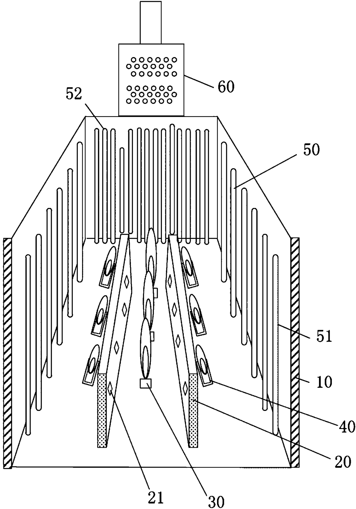
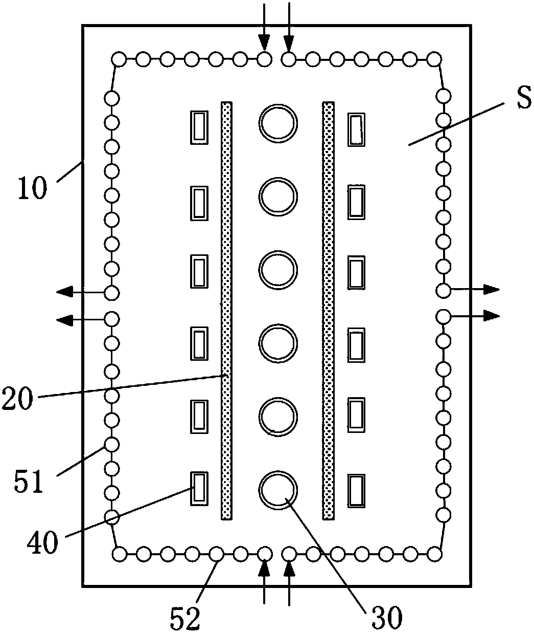
[0045] Such as image 3 As shown, the cross-section of the radiation chamber 10 is rectangular, the size is 5m×5.5m, the height of the radiation chamber 10 is 13m, the length of the first furnace tube 51 is 12m, and the outer diameter φ152mm, there are 36 pieces in total; the second furnace tube 52 The length is 12m, the outer diameter is φ152mm, and there are 28 pieces in total. The first furnace tube 51 and the second furnace tube 52 form a square annular area S, the first furnace tube 51 and the second furnace tube 52 are arranged in a single row at equal intervals, the distance between the furnace tubes is 304 mm, and 16 rows of the first furnace tube are arranged in the convection chamber 60. Three furnace tubes, the outer diameter of each third furnace tube is φ152mm, the length is 5m, the height of the middle furnace wall 20 is 2m, and the heat load of the first burner 30 accounts for 80% of the calorific value of the vertical tube square box furnace, The heat load of ...

Embodiment 2

[0047] Adopt the structure similar to embodiment 1, the difference is that, as Figure 4 As shown, the cross-section of the radiation chamber 10 is that the radiation furnace tubes 50 of 13m×6m are arranged into two square annular regions S, the height of the radiation chamber 10 is 16m, the length of the first furnace tube 51 is 15m, and the second furnace tube 52 Length 11m.


PUM


Abstract

The invention relates to the field of chemical equipment, and discloses a stand pipe square box furnace. The stand pipe square box furnace comprises a square box shaped radiation chamber, two middle furnace walls, a first combustor, a second combustor and a plurality of radiation furnace pipes, wherein the plurality of radiation furnace pipes are in the radiation chamber and are arranged into a square ring shape; the two parallel middle furnace walls are arranged in a square ring shaped region defined by the radiation furnace pipes; the first combustor is arranged between the two middle furnace walls; the second combustor is positioned on one side, far away from the first combustor, of the middle furnace walls; the height of the middle furnace walls is smaller than that of the radiation furnace pipes; the radiation furnace pipes comprise first furnace pipes arranged in the extending direction of the middle furnace walls and second furnace pipes perpendicular to the extending direction;a process medium enters the second furnace pipes and is discharged from the first furnace pipe. The middle furnace walls divide the interior of the radiation chamber into a plurality of heating regions in the height and width directions, the heat intensity peak in the height direction of the first furnace pipes is reduced, and the second furnace pipes can reach relatively high average heat intensity.

Description

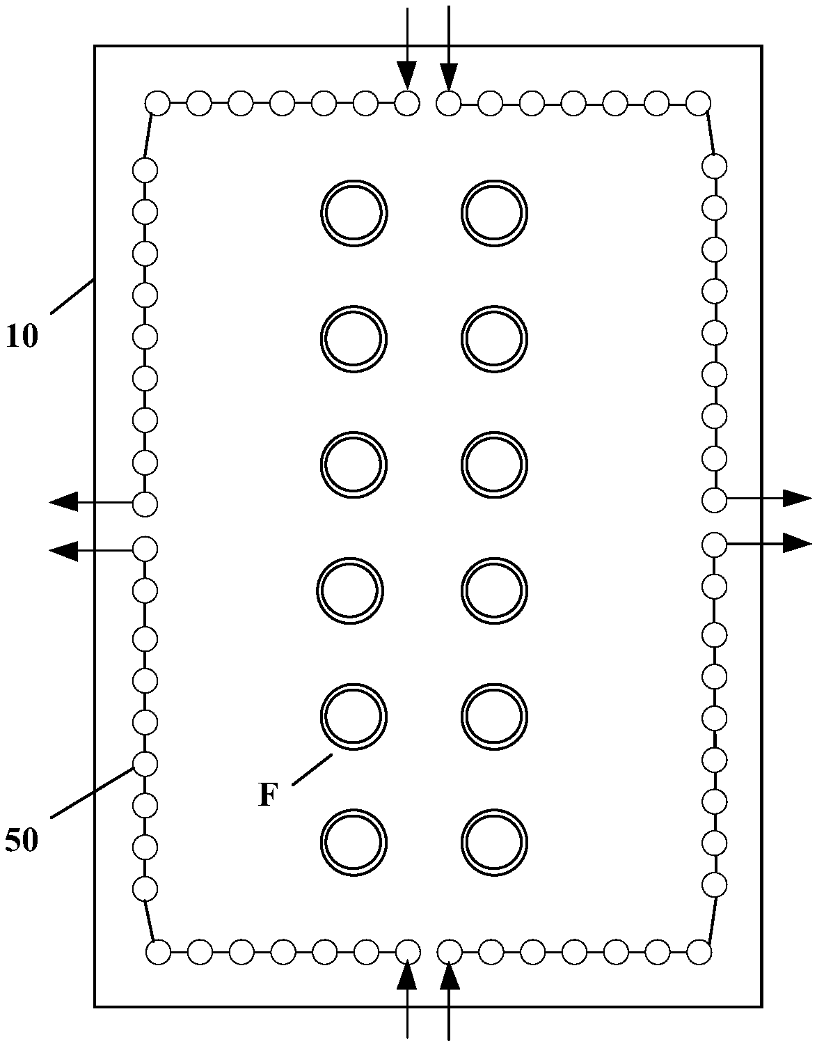
technical field [0001] The invention relates to the field of chemical equipment, in particular to a vertical tube furnace. Background technique [0002] Vertical tube square box furnace is an important heating equipment in the chemical industry. Such as figure 1 As shown, in the radiation chamber 10 of the existing vertical tube furnace (that is, the furnace tube is vertically arranged in the radiation chamber), several radiation furnace pipes 50 arranged vertically against the wall are arranged, and the burner F Arranged in rows in the cavity surrounded by radiant furnace tubes 50 , the heat of the burners F is transferred to the surrounding radiant furnace tubes 50 through radiation and convective heat transfer to heat the process medium in the radiant furnace tubes 50 . The process medium is usually divided into two or four feeds through the radiant furnace tube 50, figure 1 Four feeds are shown. [0003] The existing vertical tube square box furnace has the following...

Claims


Application Information

Patent Timeline
IPC IPC(8): F27B17/00
CPCF27B17/00
Inventor 赵日峰杨军卫李鹏沈国平王兰娟肖家治李和杰冯永生李国志肖风杰王娟
Owner CHINA PETROLEUM & CHEM CORP
Learn More