
Cylindrical tube heating furnace

A tubular heating furnace, cylindrical technology, applied in the field of cylindrical tubular heating furnace, can solve the problem of low space utilization

Inactive Publication Date: 2018-08-28
CHINA UNIV OF PETROLEUM (EAST CHINA) +2
View PDF0 Cites 1 Cited by
  • Summary
  • Abstract
  • Description
  • Claims
  • Application Information

AI Technical Summary

Problems solved by technology

[0004] The object of the present invention is to provide a cylindrical tubular heating furnace which has a relatively high space utilization rate in order to overcome the problem of low space utilization in the radiation chamber of the cylindrical tubular heating furnace in the prior art. utilization, and can increase the thermal load of the furnace

Method used


Image

  • Cylindrical tube heating furnace
  • Cylindrical tube heating furnace
  • Cylindrical tube heating furnace

Examples


Embodiment

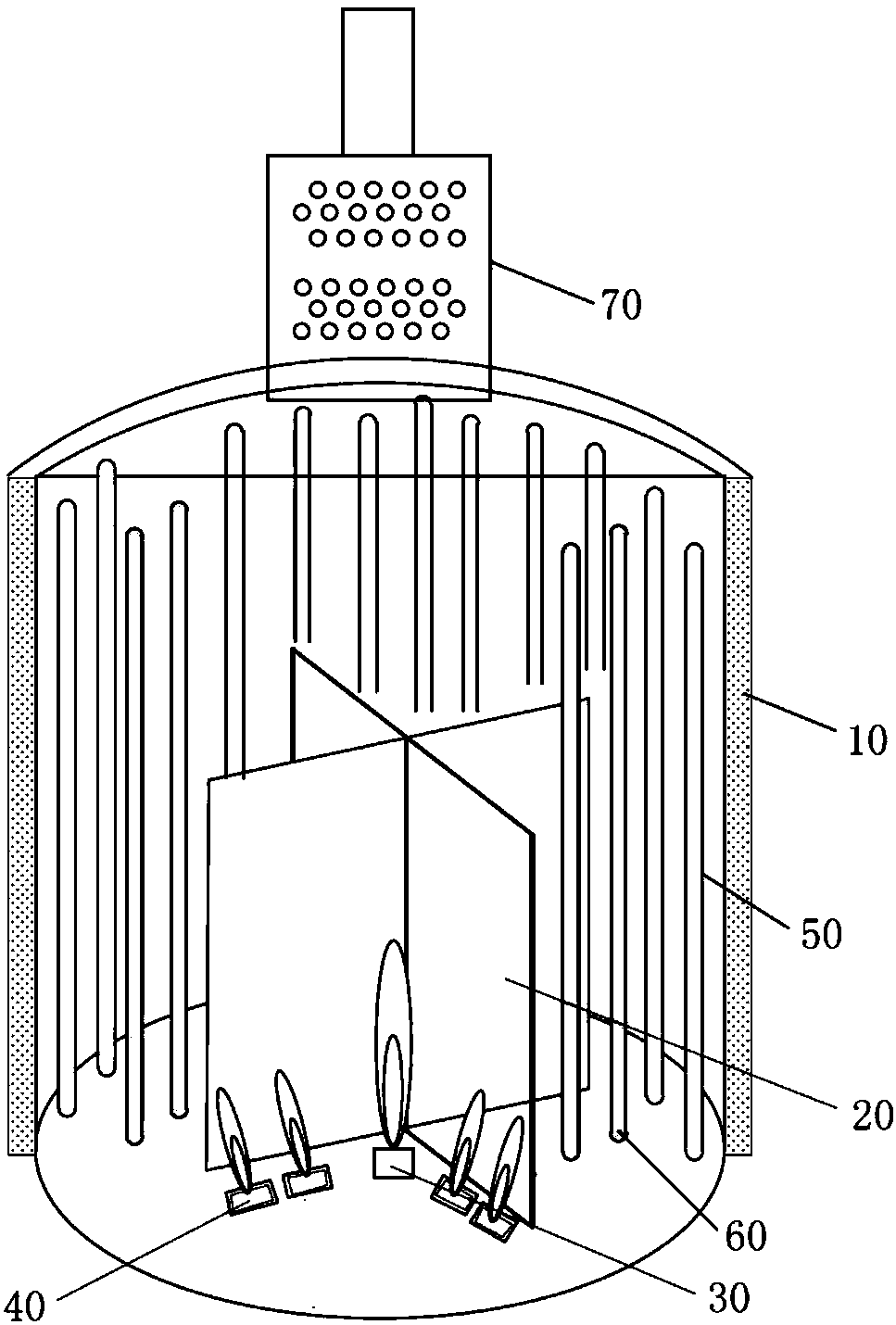
[0039] The structure of the cylindrical tubular heating furnace is as follows: image 3 and Figure 4 shown. The radiation chamber 10 is cylindrical, with a diameter of φ7650mm. The height of the radiation chamber 10 is 15m. The first furnace tube 50 and the second furnace tube 60 have the same specifications, the length is 14m, and the outer diameter is φ168mm. There are 64 vertically arranged furnace tubes. There are 50 first furnace tubes and 16 second furnace tubes 60; the third furnace tubes have an outer diameter of φ152mm and a length of 4.0m, and there are 18 rows of third furnace tubes in total. The height of the middle furnace wall 20 is 2.5m, and the length of the wall body 21 is 2.5m. The space in the radiation chamber 10 is equally divided into 4 heating zones S. The first burner 30 is a circular burner, and the total heat load accounts for the whole 80% of the calorific value of the furnace, the second burner 40 is a burner attached to the wall, and the total h...


PUM


Abstract

The invention relates to the field of chemical equipment, and discloses a cylindrical tube heating furnace. The cylindrical tube heating furnace comprises a cylindrical radiation chamber (10), a middle furnace wall (20), first combustors (30), second combustors (40), a plurality of first furnace tubes (50) and a plurality of second furnace tubes (60); the first furnace tubes (50) are arranged in the circumferential direction of the radiation chamber (10); the middle furnace wall comprises a plurality of walls (21), the plurality of walls are crossed in the middle of the radiation chamber and extend in the radial direction of the radiation chamber so as to divide a cylindrical space in the radiation chamber into a plurality of heat supply areas, the plurality of heat supply areas are separated from one another through the walls, the first combustors are arranged at the position, close to the middle part of the radiation chamber, of each heat supply area, the second combustors are arranged at the positions, close to the tail ends of the walls, and the plurality of second furnace tubes are arranged in each heat supply area. Combustors can be compactly arranged in the heat supply areas, so that the number of the combustors and the space utilization rate of the hearth are improved. According to the second furnace tubes, the heat absorption area of the furnace tubes is increased, andthe heat load of the heating furnace is improved.

Description

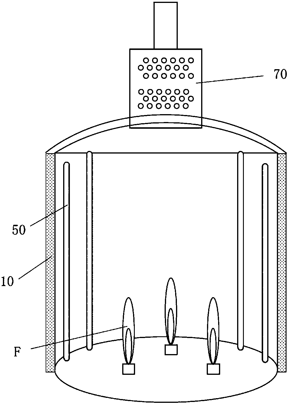
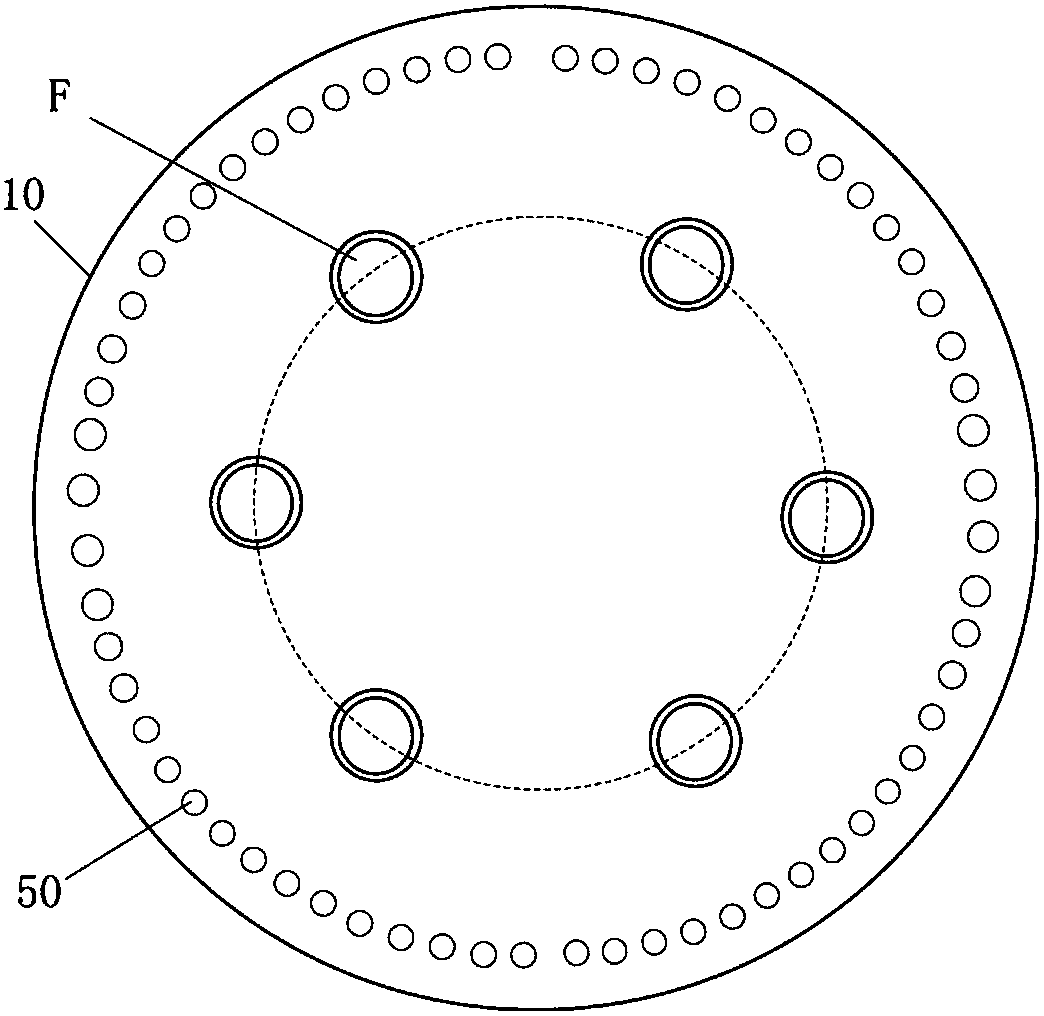
technical field [0001] The invention relates to the field of chemical equipment, in particular to a cylindrical tubular heating furnace. Background technique [0002] Cylindrical tubular heating furnace is an important heating equipment in the chemical industry. Such as figure 1 with figure 2 As shown, the existing cylindrical tubular heating furnace generally includes a convection chamber 70 and a radiation chamber 10. The radiation chamber 10 is provided with first furnace tubes 50 arranged vertically along the circumference and arranged in the radiation chamber along the circumference. The burner F, the heat of the burner F is transferred to the surrounding first furnace tube 50 through radiation and convection heat transfer, so as to heat the process medium in the first furnace tube 50 . [0003] In the existing cylindrical tube furnace, the first furnace tube 50 and the burners F are arranged circumferentially in the furnace, so that the furnace space inside the pit...

Claims


Application Information

Patent Timeline
IPC IPC(8): F27B17/00F27D99/00F23C5/08
CPCF23C5/08F27B17/0016F27D99/0035
Inventor 赵日峰杨军卫李鹏肖家治王瑜朱亚东冯永生韩艳萍蒋荣兴陈开辈肖风杰王娟
Owner CHINA UNIV OF PETROLEUM (EAST CHINA)
Learn More