Optical Pump for High Power Laser

a high-power laser and optical pump technology, applied in lasers, semiconductor lasers, solid-state devices, etc., can solve the problems of large fraction of the optical energy of flash lamps that is not utilized effectively, the wavelength range of absorption in typical gain media is limited, and the broad emission spectrum of flash lamps is a major disadvantag

Active Publication Date: 2013-08-15
PRINCETON OPTRONICS
View PDF3 Cites 48 Cited by
  • Summary
  • Abstract
  • Description
  • Claims
  • Application Information

AI Technical Summary

Benefits of technology

[0032]VCSEL pump modules may be made very compact and may be assembled with gain medium in very compact high power lasers that operate in high temperature environment. In one aspect of the invention, a compact high power solid state laser is provided for generating pulses for ignition in an internal combustion engine chamber such as for automobile engines or stationary engines used for power generation or for pulsed detonation engines (PDE) for aircraft propulsion.

Problems solved by technology

However, broad emission spectrum of flash lamps also is a major disadvantage because wavelength range for absorption in typical gain media is limited.
Therefore, a large fraction of the optical energy from the flash lamp is not utilized effectively in pumping the gain medium and part of the pump energy is transferred as heat in the gain medium giving rise to undesirable effects including thermal lensing.
Since typical gain media comprise of material that exhibit poor thermal conductivity, temperature variations in the gain medium may cause instabilities that are detrimental for high power operation in continuous wave (CW) mode, quasi-continuous mode (QCW) or in pulsed mode for example, in Q-switch mode used in applications such as wavelength conversion.
Temperature instabilities may even affect the polarization properties.
While it is well established that edge emitting semiconductor lasers and in particular, one dimension array of such lasers provide adequate optical power to pump a solid state laser, they have some limitations.
Therefore, emission from an edge emitting laser requires a complex arrangement of optical components to generate a well focused narrow beam for pumping a gain medium in end-pumping configuration.
Although pumping a gain medium in side- as well as end-pumping configurations has been demonstrated, edge emitting lasers have certain limitations.
In arrays of edge emitting lasers, the minimum distance that is allowed between each laser may be limited by the space required to accommodate the cooling arrangement.
It is also inconvenient to configure edge emitting lasers into a two-dimensional array as it requires complex assembly of edge emitter bars into stacks, as is well known in the art.
This approach has disadvantages however when increased pump energy is required.
One disadvantage of the method described in the Miesak patent is related to a practical limit to the size of a VCSEL array due to fabrication limitations.
As a result there are undesirable gaps in the incident pump beam on the laser rod.
This diffuser adds losses to the pump beam since light is diffused away from the laser rod in some areas.
An additional disadvantage is that the maximum size of the VCSEL arrays is constrained by the size of the side surface.
A second disadvantage relates to the cooling of the laser rod and the VCSEL devices.
Locating the VCSEL arrays so close to the laser rod increases the complexity of the cooling arrangement.
There are two disadvantages of this approach.
The reflection cylinder and diffusion material will cause a small amount of loss at each reflection and diffusion due to imperfections and other absorption effects.
The second disadvantage is that the laser beam intensity cross-section is not uniform but follows a more Gaussian type of distribution being highest intensity in the center and weaker intensity at the edges.
In fact, none of the prior publications describe a system that is adaptable to side-pumping and end-pumping configuration.
Furthermore, most of the prior art publications describe optical pumping methods that are particularly suited for solid state gain medium and do not disclose arrangements for other types of gain media for example, semiconductors, liquid or gel, etc.
In addition, none of the prior art publications teach or suggest a pumping method that is readily adaptable for upgrading the pump power in a modular fashion.

Method used


Image

  • Optical Pump for High Power Laser
  • Optical Pump for High Power Laser
  • Optical Pump for High Power Laser

Examples


embodiment 1700

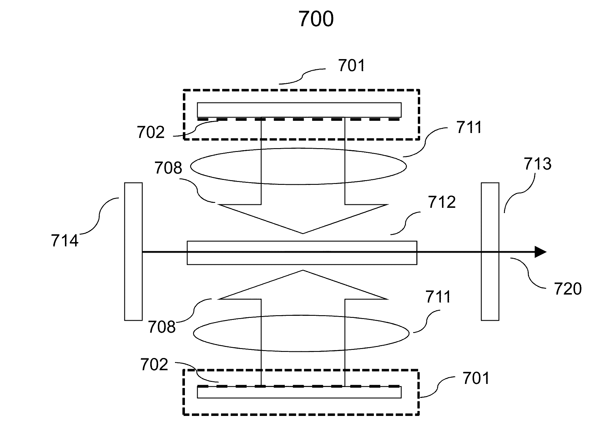
[0098]The simple co-linear configuration of an end-pumped high power laser described earlier in reference with FIG. 16 is extended to configure a dual end-pumped high power laser shown in FIG. 17. Although the basic principles of the embodiment 1700 will be described in reference with a solid state gain medium for example, a Nd:YAG crystal having a fundamental emission at 1064 nm, the same principles may be extended to other types of gain media within the broad framework. More specifically, a high power laser comprising a gain medium 1712 is placed in a laser resonant cavity constructed using a high reflectivity reflector 1713 and a partially reflective spherical curved mirror 1714 for the laser output 1720. Both ends of the gain medium are antireflective at 808 nm, coinciding respectively with the laser fundamental mode and pump wavelengths in this exemplary configuration

[0099]Two VCSEL array pump modules 1701 and 1721 pump the gain medium at its two ends. More specifically, the pu...

embodiment 1800

[0100]Another configuration for applying dual-end pumping is represented in an embodiment shown in FIG. 18. The embodiment 1800 has similar elements and functions substantially similar to the one described in reference with FIG. 17 except for the laser cavity design. The elements that are identical in FIGS. 17 and 18 are labeled using similar reference numerals and have been already described in reference with FIG. 17. Same description will not be repeated in reference with FIG. 18 for brevity. The embodiment will be described in reference with a solid state gain medium but the principles are equally applicable for other types of gain media.

[0101]In particular, a solid state gain medium 1812 is placed in a resonant cavity comprising a first reflector 1813 having a high reflectivity and a second spherical reflector 1814 that is partially reflective to transmit the laser output 1820. In this embodiment, the lasing path represented by the double headed dashed arrow, is defined by placi...


PUM


Abstract

Optical pump modules using VCSEL arrays are provided to pump optical gain media for achieving high power laser output in CW, QCW and pulse operation modes for operation. Low divergence and symmetric far-field emission from VCSELs are particularly suitable for compact arrays. VCSEL arrays configured as laser pump modules are operable at high temperatures with practically no degradation over a long period of time. VCSEL pump modules are adaptable for side- or end-pumping configurations to pump high power lasers in CW, QCW and pulse mode. Power output from VCSEL pump modules is scalable. Incorporating microlens arrays with the VCSEL arrays improve brightness of the pump modules. High power and high temperature operation of VCSEL modules make it suitable for making compact high power solid state lasers that are operable in small spaces such as, ignition of internal combustion engines, stationary power generation engines and pulsed detonation engines.

Description

BACKGROUND OF THE INVENTION[0001]1. Field of the Invention[0002]This invention relates to optical pumps for compact high power lasers and in particular, to high power optical pumps including Vertical Cavity Surface Emitting Laser (VCSEL) and arrays of VCSELs, for operating high power lasers in continuous wave (CW), Quasi Continuous Wave (QCW) and pulse operation modes.[0003]2. Description of the Related Arts[0004]Optical pumping is one of the preferred methods to operate a class of high power lasers. A high power laser typically comprise of a gain medium enclosed in a resonant feedback cavity having at least one high reflectivity surface and one partially reflective surface placed on opposite ends of the cavity, such that laser emission is emitted out of the partially reflective surface. The laser light in general is emitted along the length of the gain medium to be referred as the laser axis hereinafter for the ease of description. The gain medium may be in the form of a solid rod ...

Claims


Application Information

Patent Timeline
Patent Type & Authority Applications(United States)
IPC IPC(8): H01S3/093H01S5/023
CPCH01S3/09408H01S3/0941H01S5/423H01S5/02407H01S5/0425H01S5/02236H01L2224/32225H01L2224/48091H01L2224/48227H01L2224/48465H01L2224/4848H01L2224/73265H01S5/04257H01S5/023H01S5/0233H01S5/0235H01S5/02345H01L2924/00014H01L2924/00
Inventor VAN LEEUWEN, R.XU, BINGSEURIN, J-FGHOSH, CHUNI LALXIONG, YIHAN
Owner PRINCETON OPTRONICS
Why Eureka
Try Eureka