Thermal cycler for PCR

a cycler and cycler technology, applied in the field of computer controlled instruments, can solve the problems of increasing the total time needed to complete the amplification, wasting energy, and wasting resources, and achieve the effect of less power, less power, and less thermal non-uniformity

Inactive Publication Date: 2005-07-07
APPL BIOSYSTEMS INC
View PDF36 Cites 102 Cited by
  • Summary
  • Abstract
  • Description
  • Claims
  • Application Information

AI Technical Summary

Benefits of technology

[0010] The invention is also directed to a heatsink constructed with a perimeter trench to limit heat conduction and losses from its edges. Furthermore, the heatsink has an associated variable speed fan to assist in both maintaining a constant temperature and in cooling.
[0012] There is also provided a perimeter heater to minimize the thermal non-uniformity across the sample block. The perimeter heater is positioned around the sample block to counter the heat loss from the edges. Power is applied to the heater in proportion to the sample block temperature with more power applied when the sample block is at higher temperatures and less power applied when the sample block is at lower temperatures.
[0013] There is also provided a heated cover, designed to keep the sample tubes closed during cycling and to heat the upper portion of the tubes to prevent condensation. The heated cover applies pressure on the sample tube cap perimeter to avoid distorting the cap's optical qualities. The cover is self-aligning, using a skirt which mates with a sample tube tray.
[0014] The invention is also directed to a method and apparatus for determining an ideal temperature ramp rate which is determined so as to take advantage of sample block temperature overshoots and undershoots in order to minimize cycle time.

Problems solved by technology

Since the number of cycles is fairly large, this additional time unnecessarily heightens the total time needed to complete the amplification.
However, in these previous instruments differences in sample temperature are generated by non-uniformity of temperature from place to place within the sample metal block.
Further, there are delays in transferring heat from the sample block to the sample, and those delays differ across the sample block.
These differences in temperature and delays in heat transfer cause the yield of the PCR process to differ from sample vial to sample vial.
The problems of minimizing non-uniformity in temperature at various points on the sample block, and time required for and delays in heat transfer to and from the sample become particularly acute when the size of the region containing samples becomes large as in the standard 8 by 12 microtiter plate.
Another problem with current automated PCR instruments is accurately predicting the actual temperature of the reaction mixture during temperature cycling.
Actual measurement of the temperature of the mixture in each vial is impractical because of the small volume of each vial and the large number of vials.

Method used


Image

  • Thermal cycler for PCR
  • Thermal cycler for PCR
  • Thermal cycler for PCR

Examples


Embodiment Construction

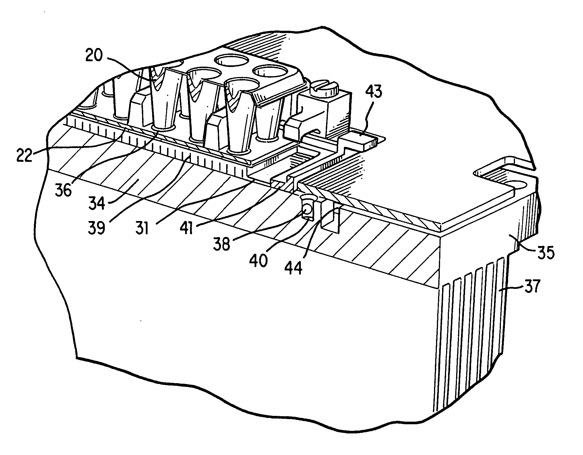
[0035] Generally, in the case of PCR, it is desirable to change the sample temperature between the required temperatures in the cycle as quickly as possible for several reasons. First the chemical reaction has an optimum temperature for each of its stages and as such less time spent at non-optimum temperatures means a better chemical result is achieved. Secondly a minimum time is usually required at any given set point which sets a minimum cycle time for each protocol and any time spent in transition between set points adds to this minimum time. Since the number of cycles is usually quite large, this transition time can significantly add to the total time needed to complete the amplification.

[0036] The absolute temperature that each reaction tube attains during each step of the protocol is critical to the yield of product. As the products are frequently subjected to quantitation, the product yield from tube to tube must be as uniform as possible and therefore both the steady-state ...


PUM

PropertyMeasurementUnit
temperaturesaaaaaaaaaa
diameteraaaaaaaaaa

Abstract

An instrument for performing highly accurate PCR employing an assembly, a heated cover and an internal computer. The assembly is made up of a sample block, a number of Peltier thermal electric devices and heat sink, clamped together. The sample block temperature is changed exclusively by the thermoelectric devices controlled by the computer. The sample block is of low thermal mass and is constructed of silver. The Peltier devices are designed to provide fast temperature excursions over a wide range. The heat sink has a perimeter trench to minimize edge losses and is adjacent to a continuously variable fan. A perimeter heater is used to improve the thermal uniformity across the sample block to approximately ±0.2° C. A heated platen pushes down onto the tube caps to apply a minimum acceptable force for seating the tubes into the block, ensuring good thermal contact with the block. The force is applied about the periphery of the tube caps to prevent distortion of the caps during thermal cycling. The platen is heated to provided thermal isolation from ambient conditions and to prevent evaporation from the surface of the sample into the upper portion of the sample tube. A control algorithm manipulates the current supplied to the thermoelectric coolers such that the dynamic thermal performance of the block can be controlled so that pre-defined thermal profiles for the sample temperature can be executed. The sample temperature is calculated instead of measured using a design specific model and equations. The control software includes calibration diagnostics which permit variation in the performance of thermoelectric coolers from instrument to instrument to be compensated for such that all instruments perform identically. The block / heat sink assembly can be changed to another of the same or different design. The assembly carries the necessary information required to characterize its own performance in an on-board memory device, allowing the assembly to be interchangeable among instruments while retaining its precision operating characteristics. The instrument has a graphical user interface. The instrument monitors the thermoelectric devices and warns of changes in resistance that may result in failure.

Description

RELATED APPLICATIONS [0001] This application is a divisional application of U.S. patent application Ser. No. 09 / 075,392, filed May 8, 1998, which is incorporated herein in its entirety by reference.FIELD OF THE INVENTION [0002] This invention pertains to the field of computer controlled instruments for performing the Polymerase Chain Reaction (PCR). More particularly, the invention pertains to automated instruments that perform the reaction simultaneously on many samples and produce very precise results by using thermal cycling. BACKGROUND OF THE INVENTION [0003] The background of the invention is substantially as stated in U.S. Pat. No. 5,475,610 which is herein incorporated by reference. [0004] To amplify DNA (Deoxyribose Nucliec Acid) using the PCR process, it is necessary to cycle a specially constituted liquid reaction mixture through several different temperature incubation periods. The reaction mixture is comprised of various components including the DNA to be amplified and a...

Claims


Application Information

Patent Timeline
Patent Type & Authority Applications(United States)
IPC IPC(8): B01L7/00G01R27/20G05D23/19H01L35/30
CPCB01L7/52B01L2300/0829B01L2300/1822B01L2300/1827H01L35/30F25B21/04F25B2321/021G01R27/205G05D23/1919C12Q1/686Y10T137/1516H10N10/13B01L3/50853
Inventor ATWOOD, JOHN G.FAWCETT, ADRIANFERRARA, KEITH S.HETHERINGTON, PAUL M.NOREIKS, RICHARD W.OLSEN, DOUGLAS E.WIDOMSKI, JOHN R.WITTMER, CHARLES M.
Owner APPL BIOSYSTEMS INC
Why Eureka
Try Eureka