Radiator, in particular for room heating

a technology for radiators and rooms, applied in the field of radiators, can solve the problems of limiting the heating difficult installation of the related electronic control units close to the radiators, etc., and achieve the effect of limiting the conduction of hea

Active Publication Date: 2017-02-21
I R C A S P A IND RESISTENZE CORAZZATE E AFFINI
View PDF14 Cites 0 Cited by
  • Summary
  • Abstract
  • Description
  • Claims
  • Application Information

AI Technical Summary

Benefits of technology

[0008]Such a solution is better employed when said container is at least partially formed by a heat dissipator adapted to disperse the heat generated by the internal circuitry defining the control unit. Furthermore, it is better applied when the container is associated with the radiator by means of insulating elements, so as to limit the conduction of the heat from the radiator to the container.

Problems solved by technology

Installing the related electronic control units close to the radiator is particularly difficult in fixed radiators (i.e. wall-mounted), the limitation of their heating being required.
Such a problem is more apparent in electric radiators controlled by a complex unit, i.e. capable of adjusting the temperature of the related radiator in relation to local or remote parameters, with particular reference to the power section of the unit, i.e. that in control of adjusting the circulating current in a coil.

Method used


Image

  • Radiator, in particular for room heating
  • Radiator, in particular for room heating
  • Radiator, in particular for room heating

Examples


Embodiment Construction

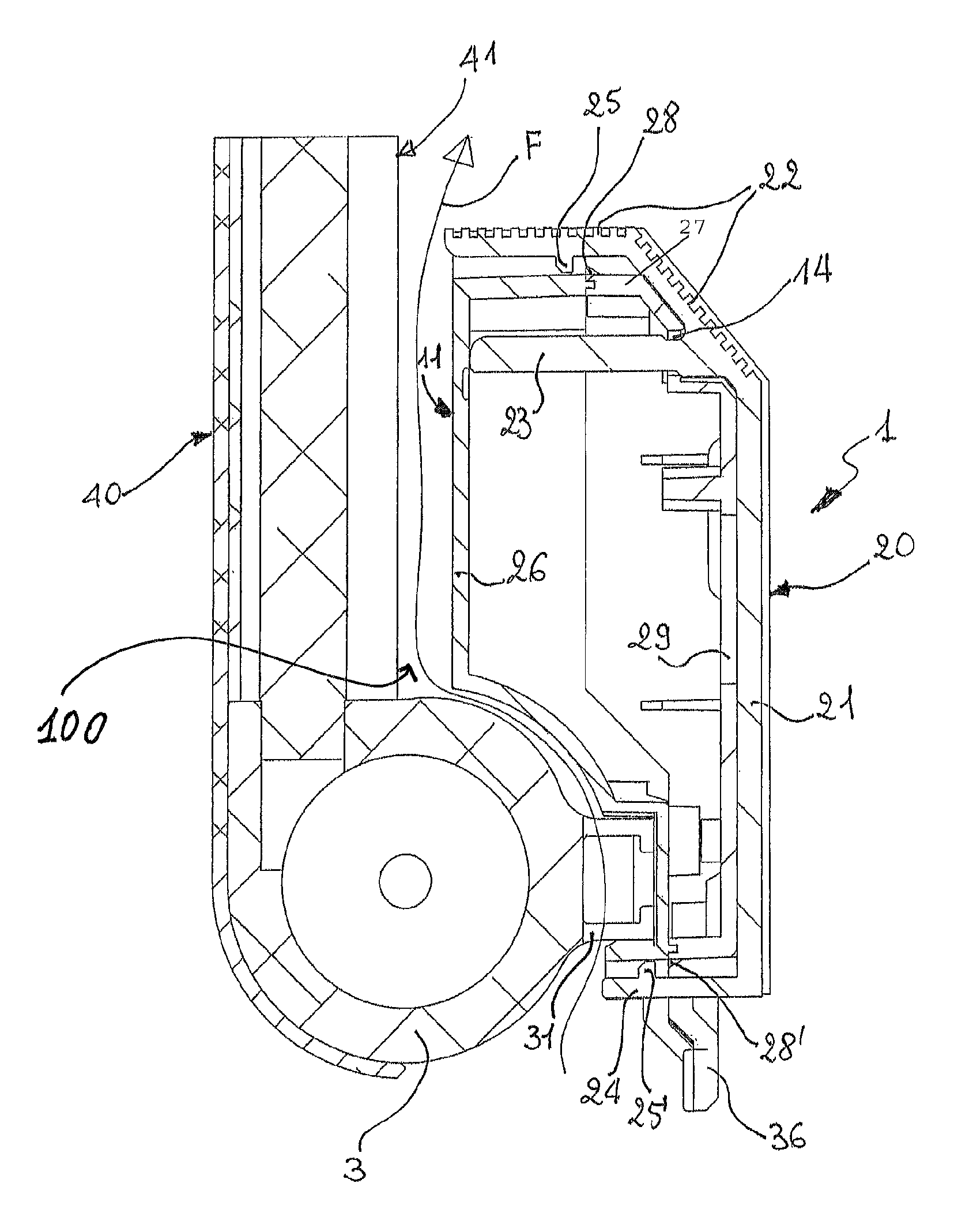
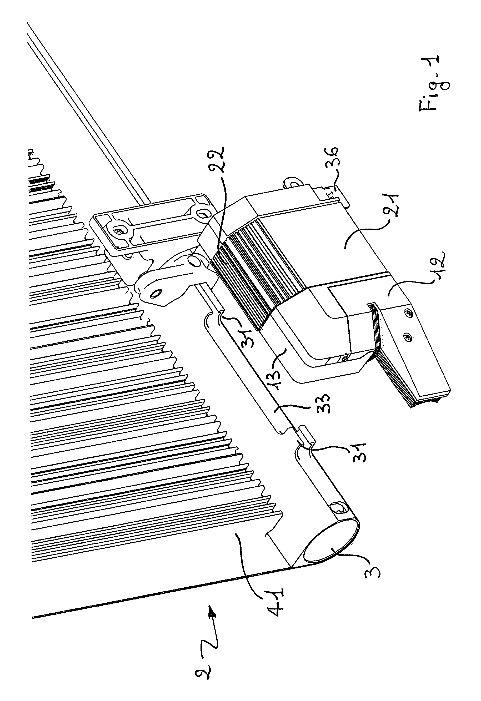
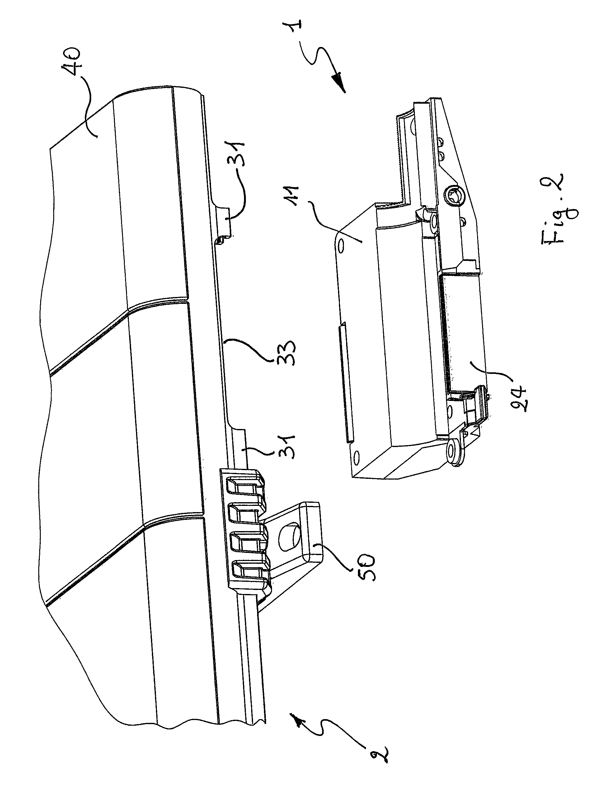
[0018]In accordance with the present invention, a radiator 2 comprises a control unit accommodated in a container 1 arranged behind the radiator, i.e. in a position out of sight. In other words, container 1 is between radiator 2 and a support structure, in particular a support wall of the radiator, when it is wall-mounted. In particular, substantially being as a rectangular parallelepiped in shape, radiator 1 comprises a first front face or radiating surface 40 and a second rear face or radiating surface 41, opposite to the first front face 40, usually having larger superficial extensions as compared to other faces of said parallelepiped. The second front face 41 is the face of the radiator facing the support wall of the radiator itself when the latter is fixed on said wall. Instead, the first front face 40 is the face with the largest extension which will be facing the room where the radiator is installed.

[0019]A unit container 1, in accordance with the present invention, comprises...


PUM


Abstract

A radiator in particular for room heating, comprising a control or measurement unit accommodated in a container integral with the radiator and positioned so as to sustain the heat from the radiator as little as possible, while exploiting a cool air flow drawn by the same to cool the internal circuitry defining the unit. Said container is conveniently spaced apart from the radiator by means of insulating elements and a part of the same container is formed by a heat dissipator to which one or more electronic power elements included in said circuitry are thermally connected.

Description

FIELD OF THE INVENTION[0001]The present invention relates to a radiator, in particular for room heating.STATE OF THE ART[0002]Radiators comprising a control unit for controlling room parameters and operating parameters of the radiators themselves are known.[0003]Installing the related electronic control units close to the radiator is particularly difficult in fixed radiators (i.e. wall-mounted), the limitation of their heating being required.[0004]Such a problem is more apparent in electric radiators controlled by a complex unit, i.e. capable of adjusting the temperature of the related radiator in relation to local or remote parameters, with particular reference to the power section of the unit, i.e. that in control of adjusting the circulating current in a coil.[0005]It is preferred that the unit be integral with the related radiator to be controlled, due to reasons of installation simplicity, but it is preferred that such a unit be separated for technical reasons so as not to comp...

Claims


Application Information

Patent Timeline
Patent Type & Authority Patents(United States)
IPC IPC(8): F24H9/20H05K7/20F24D19/02H05B1/02
CPCF24H9/2071H05K7/20409F24D19/0209F24D19/0216H05B1/0277
Inventor PETERLE, MICHELEARGENTON, MARCO
Owner I R C A S P A IND RESISTENZE CORAZZATE E AFFINI
Why Eureka
Try Eureka