
Thermo-encapsulating apparatus for providing a separator enveloping an electrode of an electrical energy storage device

a technology of electrical energy storage device and separator, which is applied in the direction of manufacturing tools, cell components, therapy, etc., can solve the problems of ineffective processing of polytetrafluoroethylene (ptfe) and similar high melting temperature fluoropolymers, subsequent capacitor or battery manufacturing processes, and product that must be scrapped, and achieves a higher melting point

Inactive Publication Date: 2011-06-14
WILSON GREATBATCH LTD
View PDF8 Cites 1 Cited by
  • Summary
  • Abstract
  • Description
  • Claims
  • Application Information

AI Technical Summary

Benefits of technology

The present invention provides an apparatus and method for cutting and heat sealing polytetrafluoroethylene (PTFE) film and other high melting separator materials around individually shaped electrodes or other components in batteries and capacitors. The apparatus includes an electrode holding fixture and a heater assembly. The heater assembly includes a dielectric base with a heating element and a heater channel formed therein. The apparatus is effective for processing high temperature separator materials and produces electrodes with tightly fitting, defect-free separator films. The technical effects of the invention include improved efficiency and accuracy in the production of batteries and capacitors, as well as improved quality and reliability of the finished product.

Problems solved by technology

Conventional thermal encapsulation systems generally are capable of cutting and sealing low melting point thermoplastic polymers such as polypropylene, but are not effective at processing polytetrafluoroethylene (PTFE) and similar high melting temperature fluoropolymers.
However, subsequent capacitor or battery manufacturing processes after electrode encapsulation, such as case welding, occur at high temperatures.
Low melting polymer separator films can be damaged during these processes, resulting in product that must be scrapped.
Additionally, the hard materials and sharp edges of the components used in these systems may damage the separator film during the encapsulation process, or during removal of the encapsulated electrode from the encapsulation apparatus.

Method used


Image

  • Thermo-encapsulating apparatus for providing a separator enveloping an electrode of an electrical energy storage device
  • Thermo-encapsulating apparatus for providing a separator enveloping an electrode of an electrical energy storage device
  • Thermo-encapsulating apparatus for providing a separator enveloping an electrode of an electrical energy storage device

Examples


Embodiment Construction

[0040]In the following description, the terms “separator film,”“separator sheet,” and “sheet of separator material” are used interchangeably, and are meant to indicate a relatively thin material that provides physical separation between a first electrode and an associated opposite polarity electrode, thereby preventing a short circuit between the electrodes. Exemplary power sources comprising opposite polarity electrodes include a capacitor or a battery.

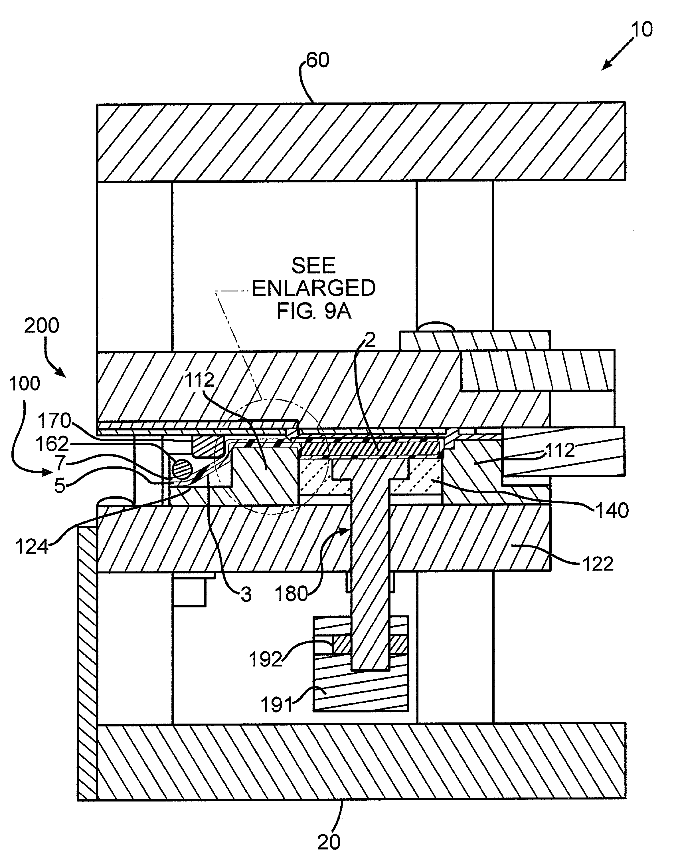
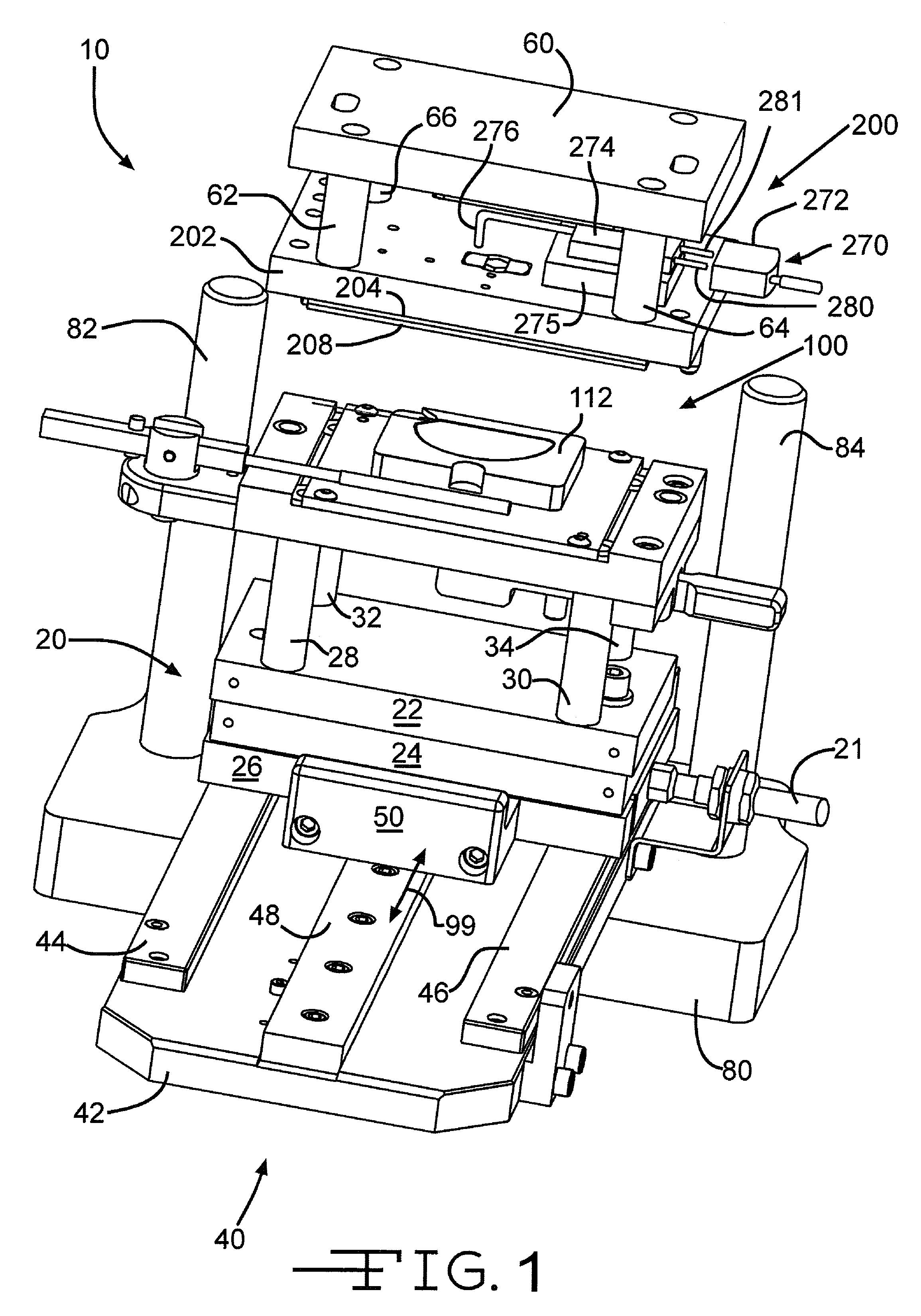
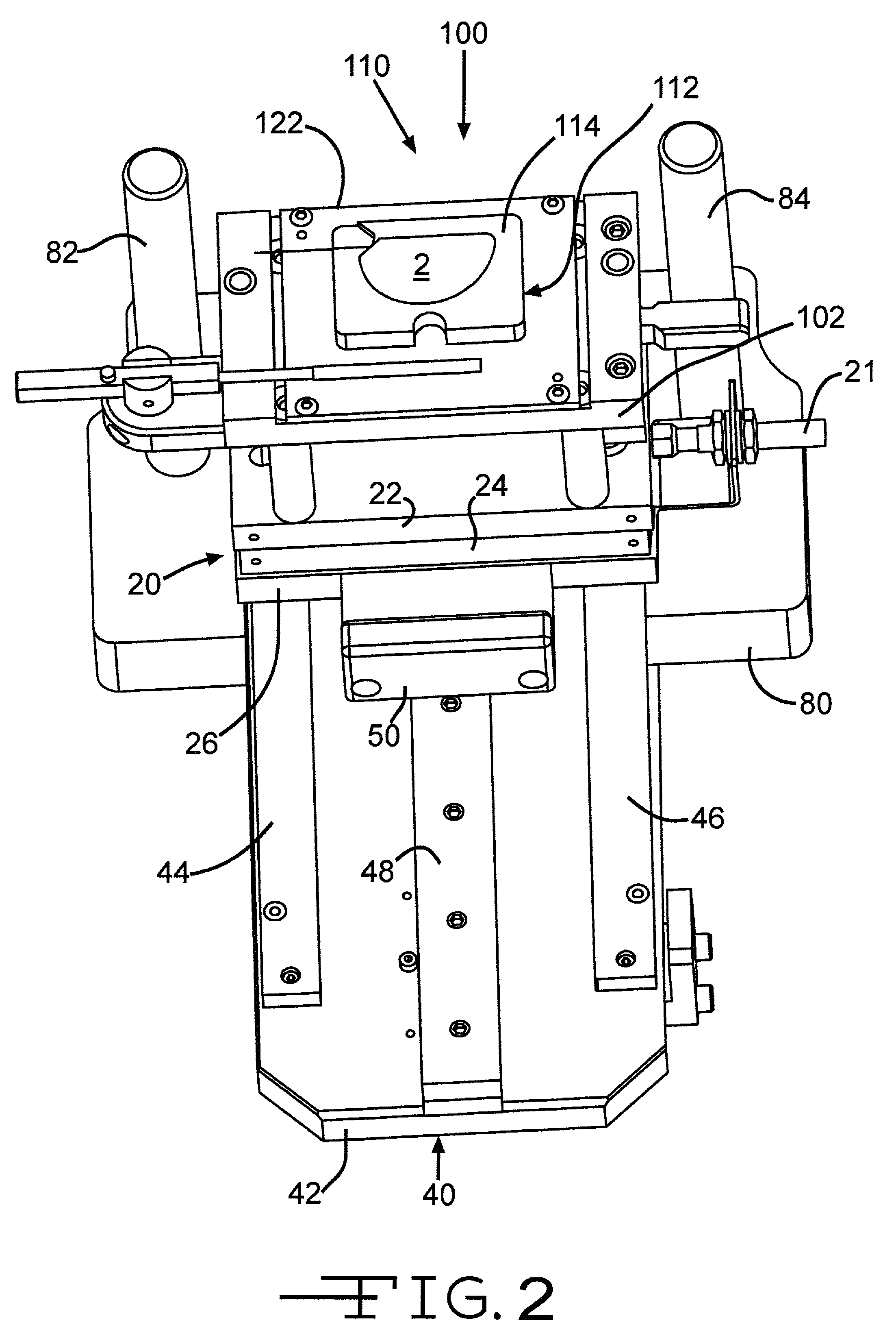
[0041]Referring now to the drawings, FIGS. 1 to 3 illustrate the present thermo-encapsulation apparatus 10 comprised of an electrode holding fixture 100 and a heater assembly 200. The electrode holding fixture 100 may be joined to a mounting base 20 comprised of one or more rigid plates 22, 24 and 26. Electrode holding fixture 100 is preferably separated from mounting base 20 by standoffs 28, 30, 32 and 34 in order to thermally isolate the fixture 100 and to provide clearance for an electrode ejection tool 190, which will be subseque...


PUM

PropertyMeasurementUnit
temperaturesaaaaaaaaaa
temperatureaaaaaaaaaa

Abstract

An apparatus and method for cutting and heat sealing separator materials enveloping individually shaped electrode is described. The electrodes can be cathodes, anodes or other active components for incorporation into batteries, capacitors, and other implantable medical devices.

Description

CROSS-REFERENCE TO RELATED APPLICATION[0001]This application claims priority from U.S. provisional application Ser. No. 60 / 888,179, filed Feb. 5, 2007.BACKGROUND OF THE INVENTION[0002]1. Field of the Invention[0003]The present invention pertains generally to an apparatus and method for manufacturing components for implantable medical devices such as batteries or capacitors. More particularly, the present invention relates in one embodiment to thermal encapsulation of a battery or capacitor electrode within a protective polymer film.[0004]2. Description of Related Art[0005]Devices for heat sealing a variety of objects within thermoplastic films are generally known. Additionally, the sealing of capacitor and battery electrodes within thermoplastic films is also known. The encapsulation of an electrode within a porous polymer film is also known. The film provides a physical separation between the electrode, and an associated opposite polarity electrode, thereby preventing a short circu...

Claims


Application Information

Patent Timeline
Patent Type & Authority Patents(United States)
IPC IPC(8): B32B37/06B32B38/04B30B5/00H01M50/423
CPCB29C65/02B29C65/18B29C65/7441B29C65/7841B29C65/7897B29C66/2442B29C66/4332B29C66/71B29C66/73115B29C66/80B29C66/81457B29C66/91231H01M2/1653H01M2/1673B29C66/81425B29C66/81415B29C66/433B29C66/91212B29C65/00A61N1/05Y10T156/1051B29C66/91421B29K2023/06B29K2027/12B29K2027/18B29K2101/12B29L2031/3406B29L2031/3468B29L2031/7532A61N1/375Y10T156/1313B29C66/961B29C66/8322B29K2995/007B29C66/81264B29C65/226B29C65/7433B29C66/1122B29C66/344B29C66/8122B29C66/81427B29C66/81265B29C66/81263B29C66/81821B29C66/81871B29C66/8242Y02E60/10B29C66/73921H01M50/46H01M50/423B29K2879/08
Inventor SEITZ, KEITH W.SCHMIT, STEVENPATTERSON, SHAWNO'CONNOR, LAURIE
Owner WILSON GREATBATCH LTD
Learn More