Feed heating device for catalytic hydrogenation equipment

A heating device and catalytic hydrogenation technology, applied in the petroleum industry, processing hydrocarbon oil, etc., can solve the problems of reducing the thermal efficiency of the furnace, increasing the fuel consumption, increasing the investment, etc. The effect of heat transfer efficiency

Active Publication Date: 2016-02-24
CHINA NAT OFFSHORE OIL CORP +2
View PDF6 Cites 0 Cited by
  • Summary
  • Abstract
  • Description
  • Claims
  • Application Information

AI Technical Summary

Problems solved by technology

The reaction feed furnaces designed in the prior art are mainly divided into two categories: one is to use the maximum possible load as the design load. According to the calibration results of some hydrogenation feed heating furnaces, the reaction feed furnace of this type is The actual operating load is often less than half of the design load, which not only increases investment and causes waste, but also has many adverse effects on the normal production operation of the heating furnace; because the furnace operating load is much smaller than the design load, the furnace only ignites during normal production With a small number of burners, it is difficult to completely close the damper of the unlit burner, causing a large amount of air to leak into the furnace. That is to say, it is difficult to control the excess air of the furnace during low-load production, and the increase of excess air will be significantly reduced. The thermal efficiency of the furnace increases the fuel consumption; at the same time, during low-load production, the ratio of the heat loss of the furnace body to the heat brought into the furnace by the fuel will also increase; the other type is to use the normal operating load as the design load. Although the reaction feed furnace can operate with high thermal efficiency under normal working conditions, it often needs to be operated in a "risky" way when encountering working conditions that require increased heat load. At this time, the furnace is prone to overheating and lining falling off and other phenomena, which seriously affect the safe operation of the reaction feeding furnace; therefore, it is sought to design a new type of reaction feeding furnace, and the side wall of the radiation chamber is designed as an inclined structure, so that the heat intensity distribution in the radiation chamber along the height direction of the radiation furnace tube More uniform to improve the heat transfer efficiency of the radiant furnace tube, making the reaction feed furnace have obvious progress significance

Method used


Image

  • Feed heating device for catalytic hydrogenation equipment
  • Feed heating device for catalytic hydrogenation equipment

Examples


Embodiment 1

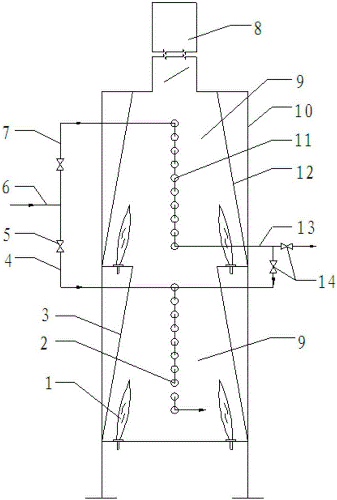
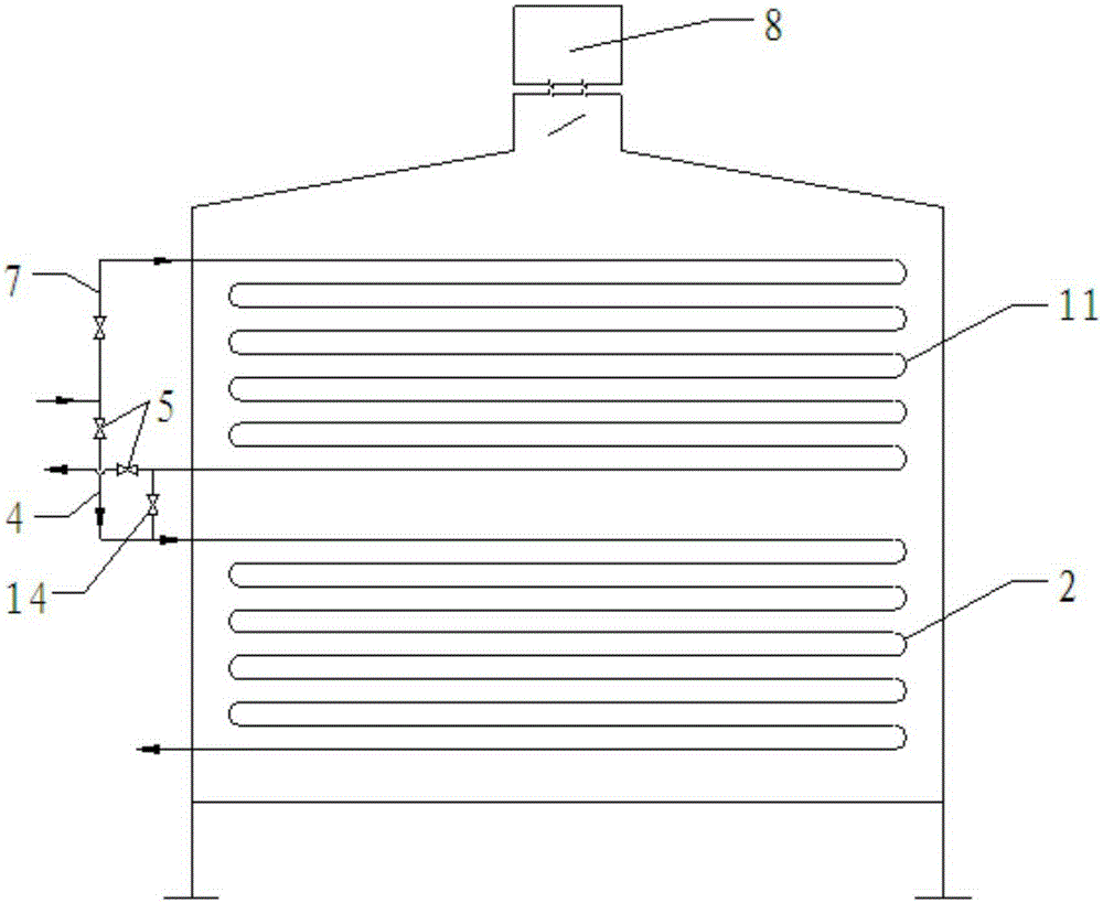
[0014] The main structure of the feed heating device involved in this embodiment includes a burner 1, a lower radiant furnace tube 2, a lower side wall 3, a lower inlet oil transfer line 4, a first valve 5, a process medium inlet pipeline 6, and an upper inlet oil transfer line. Line 7, chimney 8, radiation chamber 9, steel structure frame 10, upper radiation furnace tube 11, upper side wall 12, inter-pipe oil transfer line 13 and second valve 14, with the steel structure frame 10 as the main body to form an inner hollow inlet The interior of the material heating device is distributed with interconnected chimneys 8 and radiation chambers 9 from top to bottom. The radiation chamber 9 is formed by staggered butt joints of upper side walls 12 and lower side walls 3. Both upper side walls 12 and lower side walls 3 are It is arranged obliquely and has the same symmetrical structure. The angle between the upper side wall 12 and the lower side wall 3 and the vertical direction is 6-20...


PUM

PropertyMeasurementUnit
angleaaaaaaaaaa

Abstract

The invention belongs to the technical field of petrochemical industry heating equipment and relates to a feeding heating device of catalytic hydrogeneration equipment. A chimney and an irradiation chamber which are distributed in the feeding heating device are communicated with each other, the irradiation chamber is enclosed by the upper side wall and the lower side wall which are obliquely arranged and adopt symmetric and identical structures in a staggered abutting way, an upper irradiation furnace pipe and a lower irradiation furnace pipe are arranged on a central frame in the irradiation chamber, and burners are respectively arranged at the bottoms of the two sides of the upper side wall and the lower side wall and used for uniformly transmitting heat toward the upper irradiation furnace pipe and the lower irradiation furnace pipe; a between-pipe oil transferring line with a second valve is arranged between the upper irradiation furnace pipe and the lower irradiation furnace pipe, the upper irradiation furnace pipe and the lower irradiation furnace pipe are respectively communicated and abutted with a technical medium inlet pipeline through an upper inlet oil transferring line and a lower inlet oil transferring line, and first valves are connected to both the upper inlet oil transferring line and the lower inlet oil transferring line. The device has the advantages of simple structure, scientific design, small land occupying area, low manufacture cost and environment-friendliness in use.

Description

Technical field: [0001] The invention belongs to the technical field of heating equipment in the petrochemical industry, and relates to a feed heating device for catalytic hydrogenation equipment, in particular to a reaction feed furnace, which can be adjusted and set according to various working conditions of medium flow and heat load changes in the pipe. And can run safely and efficiently. Background technique: [0002] At present, with the increasing trend of heavy and inferior crude oil and the increasingly stringent requirements of environmental protection laws and regulations around the world, oil refineries are increasingly demanding to adopt clean production processes and produce clean fuels. Catalytic hydrogenation as An important link and process of petroleum processing is of great significance for improving the depth of crude oil processing, rationally utilizing petroleum resources, improving product quality, increasing light oil yield and reducing air pollution, ...

Claims


Application Information

Patent Timeline
Patent Type & Authority Patents(China)
IPC IPC(8): C10G49/00
Inventor 于连兴吴振松王金昌刘福生陈明华王龙波康平
Owner CHINA NAT OFFSHORE OIL CORP
Why Eureka
Try Eureka