
Display panel and display device

A display panel and switch technology, which is applied to static indicators, instruments, semiconductor devices, etc., can solve the problems of unbalanced parasitic capacitance of pixel units, large viewing angle deviation of display devices, vertical bright and dark lines, etc., to solve the problem of large viewing angle deviation. Effect

Active Publication Date: 2020-05-08
HKC CORP LTD
View PDF3 Cites 0 Cited by
  • Summary
  • Abstract
  • Description
  • Claims
  • Application Information

AI Technical Summary

Problems solved by technology

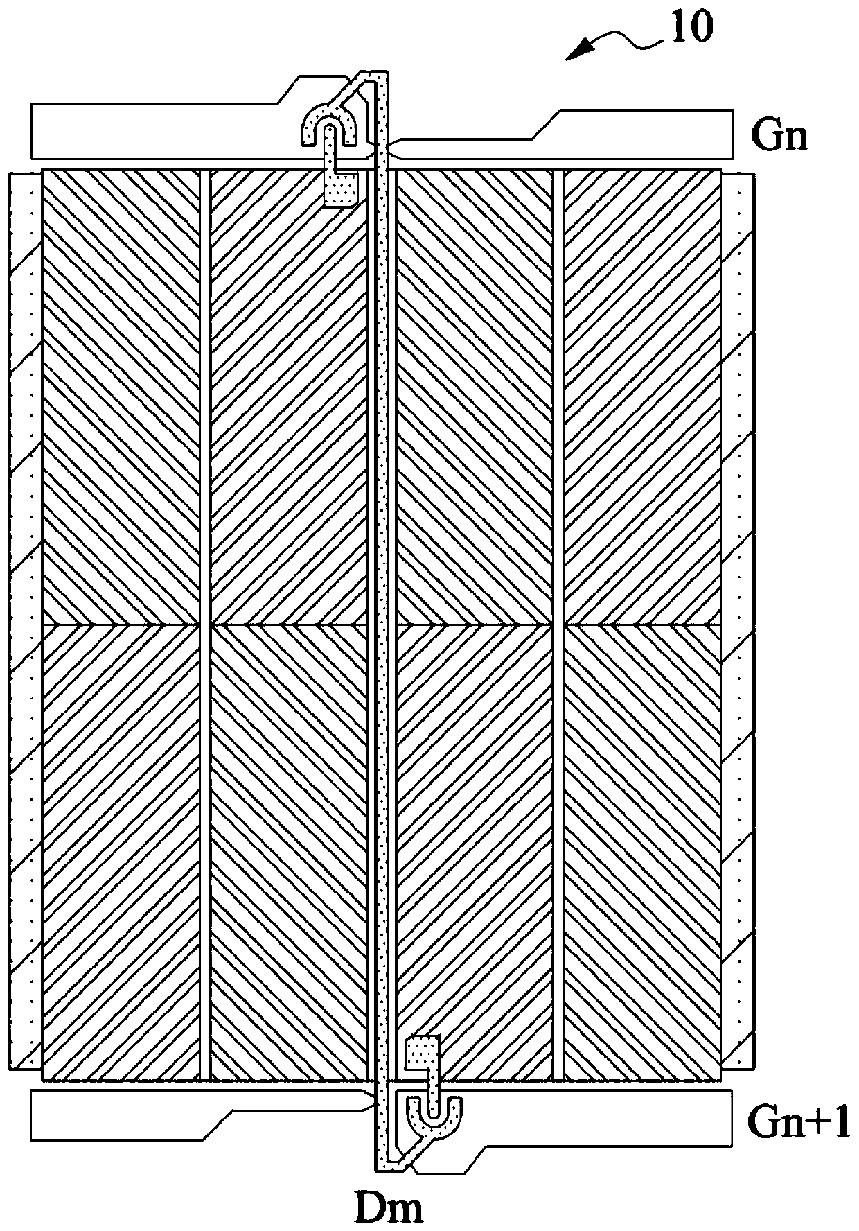
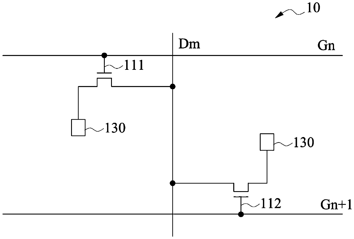
However, this technology also has certain defects. Because the same data line connects two columns of pixel units, and the doubled number of scan lines shortens the scan time of the pixel unit, it is prone to inconsistent charging efficiency, unbalanced parasitic capacitance between pixel units and signal Waveform delay and distortion and other problems, and cause the display device to appear large-view angle deviation, vertical bright and dark lines, etc.

Method used


Image

  • Display panel and display device
  • Display panel and display device
  • Display panel and display device

Examples


Embodiment Construction

[0032] The following descriptions of the various embodiments refer to the attached drawings to illustrate specific embodiments that the present application can be implemented in. The directional terms mentioned in this application, such as "up", "down", "front", "rear", "left", "right", "inside", "outside", "side", etc., are for reference only The orientation of the attached schema. Therefore, the directional terms used are used to illustrate and understand the application, but not to limit the application.

[0033] The drawings and descriptions are to be regarded as illustrative in nature and not restrictive. In the figures, structurally similar units are denoted by the same reference numerals. In addition, the size and thickness of each component shown in the drawings are arbitrarily shown for understanding and convenience of description, but the present application is not limited thereto.

[0034] In the drawings, the thickness of layers, films, panels, regions, etc., ar...


PUM


Abstract

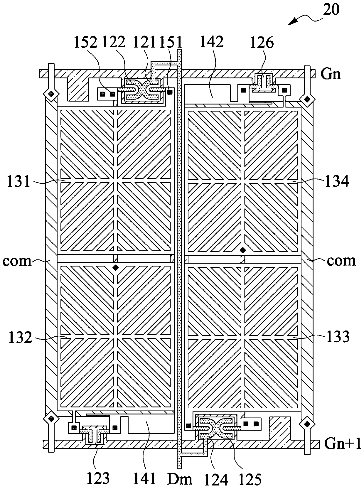
The present application provides a display panel and a display device. The display panel includes a pixel structure, and the pixel structure includes a plurality of pixel groups, and the pixel group includes: a first switch whose second end is coupled to the first main pixel; a second switch whose The second end is coupled to the first sub-pixel; the third switch, the second end of which is coupled to the first sub-pixel; the first capacitor, one end is coupled to the first end of the third switch, and the other end is coupled to the common electrode; the fourth switch , the second end of which is coupled to the second main pixel; the fifth switch, whose second end is coupled to the second sub-pixel; the sixth switch, whose second end is coupled to the second sub-pixel; the second capacitor, one end of which is coupled to the second sub-pixel The first ends of the six switches are coupled to the common electrode. The first, second and sixth switches are coupled to the nth scan line, and the third, fourth and fifth switches are coupled to the n+1th scan line.

Description

technical field [0001] The present application relates to the display field, in particular to a display panel and a display device. Background technique [0002] Liquid crystal display devices have the advantages of low cost, low power consumption and high performance, and are widely used in fields such as electronics and digital products. However, the driving of the pixel units in the display device needs to be realized by driving the corresponding scanning lines and data lines through the gate driving circuit and the source driving circuit. In order to further improve user experience and save costs, various manufacturers have developed many manufacturing technologies related to the display field, such as HSD (Half Source Driver, Half Source Driver) technology. [0003] HSD technology, which halves the number of data lines and doubles the number of scanning lines, so that each data line is connected to two columns of adjacent pixel units. Through this technology, half of t...

Claims


Application Information

Patent Timeline
Patent Type & Authority Patents(China)
IPC IPC(8): G02F1/1362G09G3/36
CPCG02F1/13624G02F1/136286G09G3/3614G02F1/133707G02F1/136213H01L27/1255G02F1/134354G02F1/134345G02F2201/40G09G3/3688G09G2300/0465G09G2300/0809G09G2310/0202G09G2310/0251G09G2310/0283G09G2320/0242H01L27/124
Inventor 黄北洲
Owner HKC CORP LTD
Learn More