Operation mechanism of high-voltage vacuum load switch
A technology of vacuum load and operating mechanism, which is applied in high-voltage/high-current switches, high-voltage air circuit breakers, electric switches, etc., can solve the problems of high difficulty in opening and closing operations, disengagement, and failure of opening and closing, and achieves simple and convenient operation. Short opening and closing process, smooth clutch effect
- Summary
- Abstract
- Description
- Claims
- Application Information
AI Technical Summary
Problems solved by technology
Method used
Image
Examples
Embodiment 1
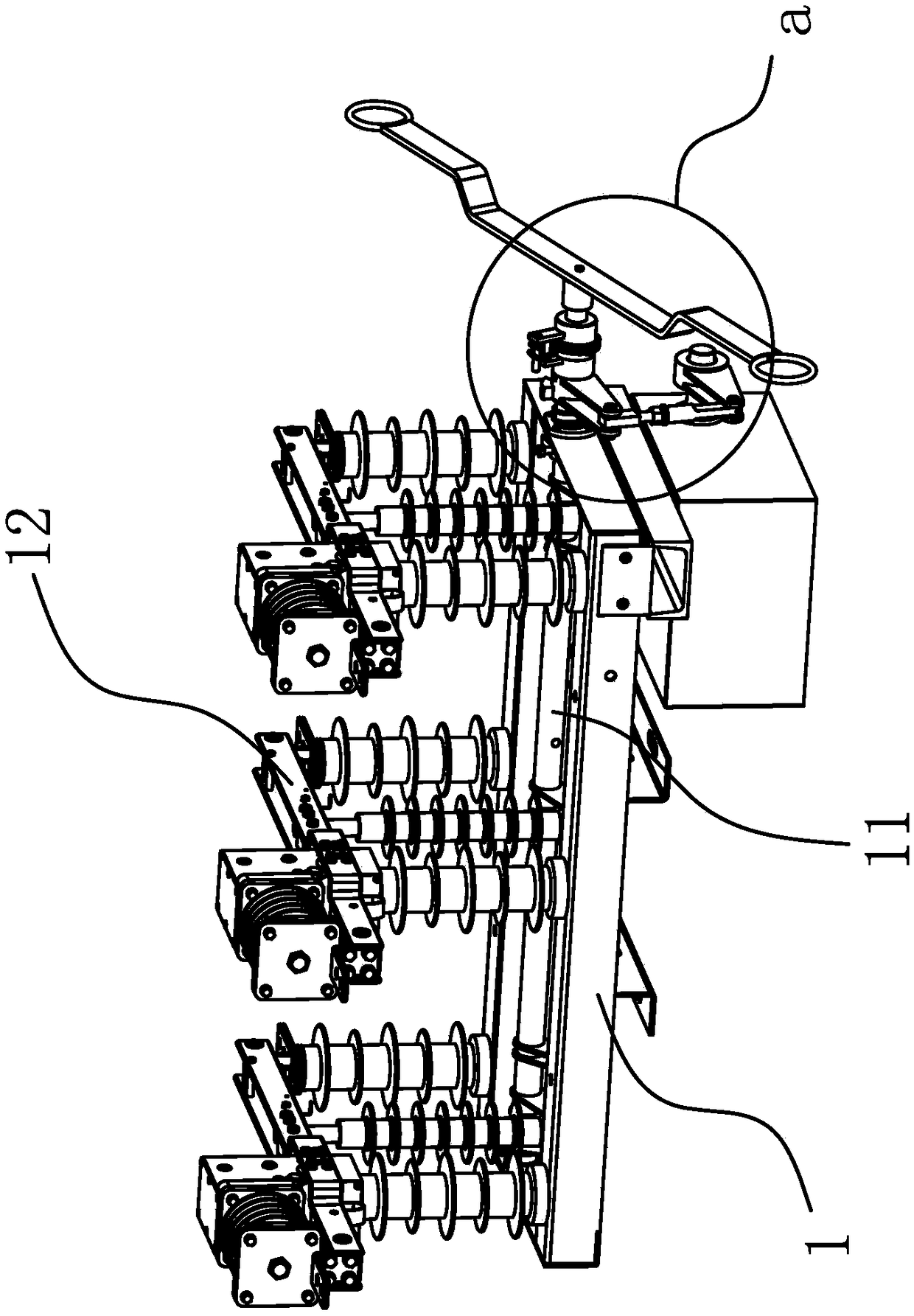
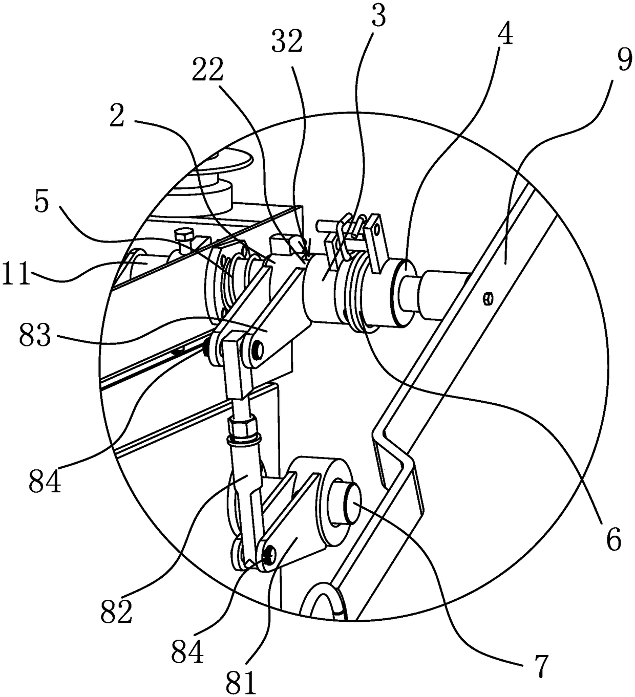
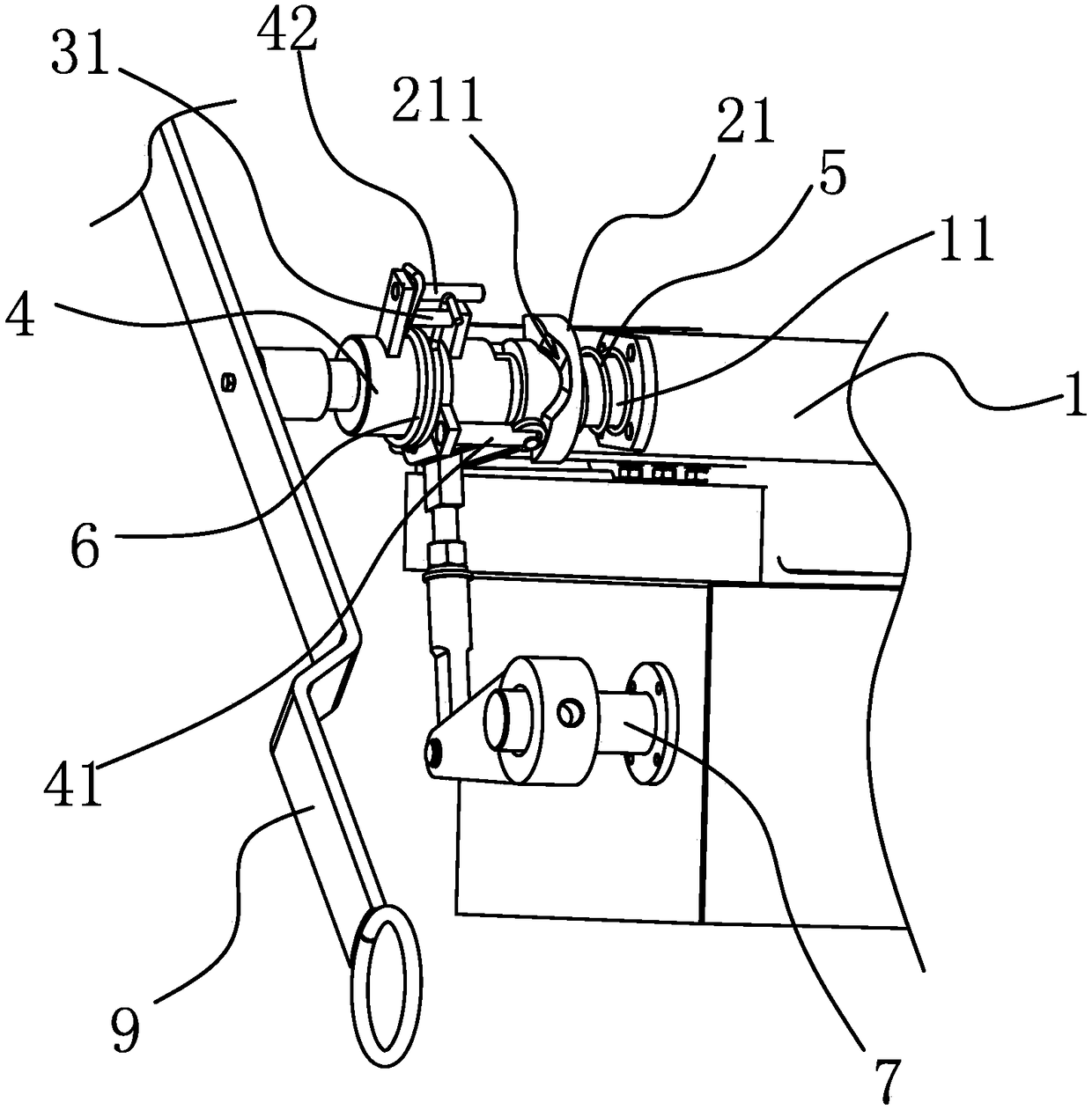
[0027] Such as figure 1 As shown, the high-voltage vacuum load switch 1 includes a switch shaft 11, on which three knife switches 12 are arranged, and turning the switch shaft 11 can drive the knife switches 12 to realize circuit on-off. The operating mechanism of the high-voltage vacuum load switch 1 includes a manual sleeve 4, a fixing part 3 and an electric sleeve 2. Both the manual sleeve 4 and the electric sleeve 2 are sleeved on the switch shaft 11 and can rotate relative to the switch shaft 11. The part 3 is fixedly connected with the switch shaft 11 and is located between the manual sleeve 4 and the electric sleeve 2. The electric sleeve 2 is sleeved and engaged with the fixed part 3, so that the electric sleeve 2 can drive the switch shaft 11 to rotate under the drive of the motor. To switch the high-voltage vacuum load switch 1, the manual sleeve 4 and the fixed part 3 are connected through a flexible connector, and a cam mechanism is provided between the manual slee...
Embodiment 2
[0033] The technical solution of this embodiment is basically the same as that of Embodiment 1, the difference is that the end surface of the electric sleeve 2 close to the fixed part 3 has several triangular blocks protruding toward the side of the fixed part 3, these triangular blocks The blocks are evenly distributed around the switch shaft 11, and the end of the fixed block close to the electric sleeve 2 is also provided with a card slot that matches the above-mentioned triangular block, so that the electric sleeve 2 and the fixed piece 3 are clamped. Of course, the positions of the triangular block and the slot can be interchanged, and the triangular block can also be replaced by an arc-shaped block.
Embodiment 3
[0035] The technical solution of this embodiment is basically the same as that of Embodiment 1. The difference is that in this embodiment, the flexible connector is a tension spring, and the two ends of the tension spring are connected to the first fixing rod 31 and the first fixing rod 31 of the fixing member 3 respectively. The second fixed rod 42 of manual sleeve 4 is connected.
PUM
 Abstract
Description
Claims
Application Information
 - R&D
- Intellectual Property
- Life Sciences
- Materials
- Tech Scout
- Unparalleled Data Quality
- Higher Quality Content
- 60% Fewer Hallucinations
Browse by: Latest US Patents, China's latest patents, Technical Efficacy Thesaurus, Application Domain, Technology Topic, Popular Technical Reports.
© 2025 PatSnap. All rights reserved.Legal|Privacy policy|Modern Slavery Act Transparency Statement|Sitemap|About US| Contact US: help@patsnap.com


