A working method equipped with an airborne multi-stage airbag cooperative buffer device

A cushioning device and working method technology, applied in launching devices, transportation and packaging, aircraft parts, etc., can solve the problems of limited effective buffering stroke, slow outward exhaust speed, damage to airborne equipment, etc., to increase the effective buffering stroke, Enhance the cushioning effect and ensure the effect of safe landing

Active Publication Date: 2021-07-27
CHANGSHA UNIVERSITY OF SCIENCE AND TECHNOLOGY
View PDF7 Cites 0 Cited by
  • Summary
  • Abstract
  • Description
  • Claims
  • Application Information

AI Technical Summary

Problems solved by technology

However, in the process of equipment airborne landing buffer, if the vent hole of the airbag buffer device is too large, there will be a problem that the airborne equipment will directly touch the ground; If the exhaust speed is too slow, the airbag will explode, which will cause fatal damage to the airborne equipment
[0006] In order to overcome the shortcoming that the single-chamber airbag cushioning device is easy to explode, a small part of the prior art has used the technical scheme of the double-chamber airbag cushioning device: as the patent "multi-stage airbag combined buffering device" with the publication number CN1923617A, but this multiple The combined cushioning device of the first-stage airbag adopts a nested structure, which results in a limited effective buffer stroke; as the patent "dual-chamber airbag cushioning device" with the publication number CN1923618A, although this airbag cushioning device adopts the top air chamber of the airbag and the base air However, there is no other buffer device between the top air chamber and the bottom air chamber of the airbag, which still results in a limited effective buffer stroke, and the top air chamber and the bottom air chamber of the airbag are two separate independent air chambers, resulting in two The air chamber cannot coordinately buffer the airborne equipment, so it cannot play a good buffering effect on the airborne equipment

Method used


Image

  • A working method equipped with an airborne multi-stage airbag cooperative buffer device
  • A working method equipped with an airborne multi-stage airbag cooperative buffer device
  • A working method equipped with an airborne multi-stage airbag cooperative buffer device

Examples


Embodiment Construction

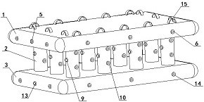
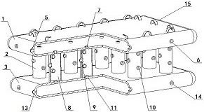
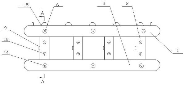
[0030] As shown in the figure: an operation method of equipping a multi-stage airbag collaborative buffer, the multi-stage airbag coordination means including an upper air bag 1, an airbag tube 2, and a vacuum capsule 3; the present invention adopts an airbag 1, an airbag tube The column 2 and the lower airbag 3 are superimposed; the upper airbag 1 is provided to provide a buckle ring device 15 and a airborne equipment connection; the upper airbag 1 surface is provided with an upper airbag pneumatic valve 5, and the upper airbag 1 is an upper air bag cavity 4, an upper airbag 1 Ten airbag exhaust valves 6 are provided, and the upper airbag 1 is provided with a combined exhaust valve one 7 with an overlapping joint of each airbag tube 2 surface.

[0031] As shown in the figure: 2 numbers of airbag tube columns are 12, the airbag tube 2 is disposed between the upper airbag 1 and the lower airbag 3 to increase the effective buffering stroke; each airbag tube 2 is provided with an air...


PUM


Abstract

The invention discloses a working method for equipping an airborne multi-stage airbag cooperative buffer device. The multi-stage airbag cooperative buffer device includes an upper airbag, an airbag column and a lower airbag; The air valve exhausts and relieves pressure to the outside, and it can also exhaust air to the airbag column through the combined exhaust valve, and the airbag column expands to achieve a first-level buffer; the airbag column can exhaust pressure outward through the airbag column exhaust valve , the lower airbag can also be exhausted through the joint exhaust valve two, and the lower airbag can be inflated to realize the second level of cushioning; the lower airbag can exhaust the pressure to the outside through the lower airbag exhaust valve to achieve the third level of buffering; after the equipment is airborne and landed safely , the airbag device can be deflated, which is convenient for storage and storage; the multi-stage buffer method of the multi-stage airbag cooperative buffer device in the present invention can not only prevent the airborne equipment from directly touching the ground, but also realize the multi-stage release of the internal pressure of the airbag to prevent the airbag from bursting. And make sure the airborne equipment lands safely.

Description

Technical field [0001] The present invention relates to the field of equipment airborne safety, and more particularly to a method of working with an airborne multi-stage airbag synergistic buffer device. Background technique [0002] The airbag buffer has been widely used in the technical field of equipment airborne, drone recycling, aerospace returns due to light weight and good energy efficiency, and has become an important part of equipment security. [0003] During the actual equipment airborne landing process, the cushioning effect of the existing airbag buffer is limited and there is the following issues. [0004] Existing airborne equipment is equipped with a single air chamber airbag buffer device, thereby causing the setting of the initial buffer air pressure of the gas chamber to be too single and there is limitations, resulting in a limited buffer effect. [0005] The existing single air chamber airbag buffer is exhausted outwardly through the exhaust hole to achieve a...

Claims


Application Information

Patent Timeline
Patent Type & Authority Patents(China)
IPC IPC(8): B64D1/14
CPCB64D1/14
Inventor 刘鑫董建业张志勇吴迪王昕宇张远洋
Owner CHANGSHA UNIVERSITY OF SCIENCE AND TECHNOLOGY
Why Eureka
Try Eureka