Supercharge Your Innovation With Domain-Expert AI Agents!

Zooming device

A technology for adjusting rings and bodies, applied in installation, optics, instruments, etc., can solve problems such as increased man-hours for damaged products, unsmooth operation of the device, and scratches on the inner cylinder 30 and positioning screws 50

Active Publication Date: 2018-07-27
SINTAI OPTICAL SHENZHEN CO LTD +1
View PDF15 Cites 0 Cited by
  • Summary
  • Abstract
  • Description
  • Claims
  • Application Information

AI Technical Summary

Problems solved by technology

[0005] Conventional sights often use the above-mentioned existing zoom device 1. When assembling, the main body 10, the outer cylinder 20, the inner cylinder 30 and the magnification adjustment ring 40 are usually assembled first, and then the set screw 50 is installed and locked. However, since the positioning hole 25 on the outer cylinder 20 cannot be seen directly from the appearance, and the material of the positioning screw 50 (for example, iron metal) is harder than the material of the outer cylinder 20 (for example, aluminum alloy), the hardness is higher. If the position of the positioning hole 25 is not aligned during the locking process, it may cause damage to the positioning hole 25 or its surroundings. In addition, if the debris generated after the damage penetrates into the outer cylinder 20 and the inner cylinder 30 through the positioning hole 25 In between, it will cause the entire device to not move smoothly, so it must be dismantled and cleaned, which will increase damage and man-hours
[0006] Furthermore, traditional sights often use a bounce adjustment piece to adjust the inclination angle of the outer cylinder 20 and the inner cylinder 30 relative to the body 10 to perform bounce correction. When the inclination angle of the cylinder 30 changes, there may be an interference transition between the set screw 50 and the inner cylinder 30, causing the inner cylinder 30 to be scratched by the set screw 50

Method used


Image

  • Zooming device
  • Zooming device
  • Zooming device

Examples


Embodiment Construction

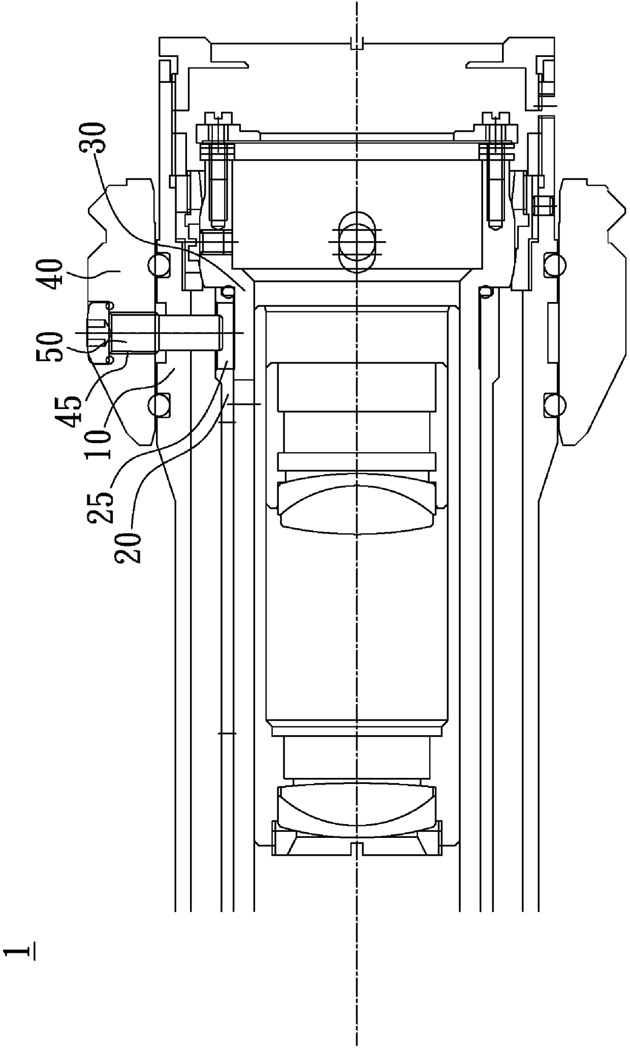
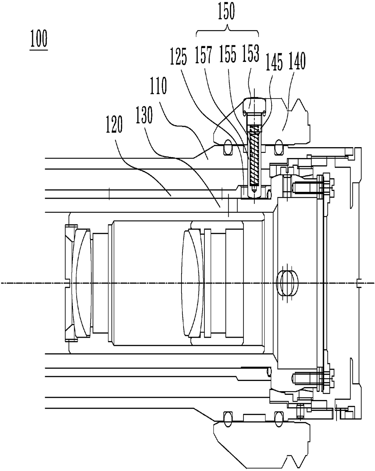
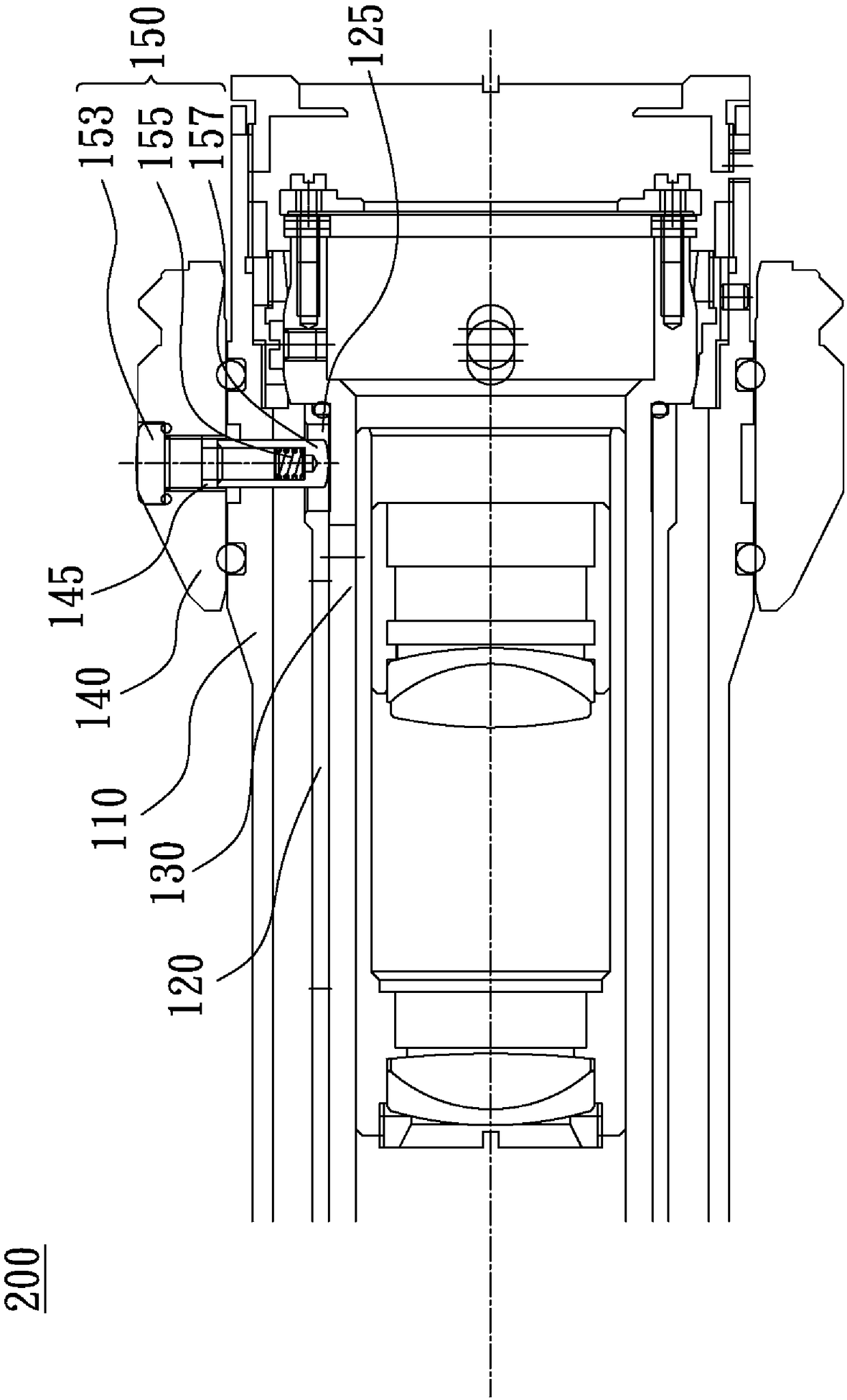
[0027] see figure 2 , figure 2 It shows a structural diagram of one embodiment of the zoom device of the present invention. In this embodiment, the zoom device 100 includes a main body 110, an outer cylinder 120, an inner cylinder 130, an adjustment ring 140 and an adjustment ring positioning member 150, wherein the rotation adjustment The ring 140 can drive the outer cylinder 120 to rotate relative to the body 110 and the inner cylinder 130 . The assembly of these components is detailed below:

[0028] The inner cylinder 130 is disposed inside the body 110 , the outer cylinder 120 is rotatably sleeved outside the inner cylinder 130 , the positioning hole 125 is formed on the outer cylinder 120 , and the adjustment ring 140 is rotatably sleeved outside the body 110 . The adjusting ring positioning member 150 includes a fixing member 153, an elastic body 155 and a positioning cylinder 157. The positioning cylinder 157 can move through the body 110 and the positioning hole 1...


PUM


Abstract

The invention relates to a zooming device comprising a body, an outer cylinder, an inner cylinder, an adjusting ring and an adjusting ring positioning member. The inner cylinder is arranged inside thebody and a positioning hole is formed in the outer cylinder. The outer cylinder sleeves the inner cylinder in a rotatable manner. The adjusting ring sleeves the body in a rotatable manner and consists of a fixed member, an elastomer, and a positioning cylinder; the positioning cylinder passes through the body and the positioning hole and is abutted against the peripheral surface of the inner cylinder; the fixed member is arranged at the adjusting ring; and one end of the elastomer is abutted against the fixed member and the other end is abutted against the inside of the positioning cylinder.When the adjusting ring rotates, the outer cylinder is driven to make rota6tion relative to the body and the inner cylinder.

Description

technical field [0001] The invention relates to a zoom device, in particular to a zoom device using a two-stage adjusting ring positioning member. Background technique [0002] see figure 1 , figure 1 It shows the structural diagram of the existing zoom device 1, the zoom device 1 includes a main body 10, an outer cylinder 20, an inner cylinder 30, a magnification adjustment ring 40 and a positioning screw 50, wherein the rotation of the magnification adjustment ring 40 can drive the outer cylinder 20 to be opposite to each other. When the body 10 and the inner cylinder 30 rotate, the assembly of these components is described in detail below: [0003] Such as figure 1 As shown, the inner cylinder 30 is disposed inside the body 10 , the outer cylinder 20 is rotatably sleeved on the outside of the inner cylinder 30 , the positioning hole 25 is formed on the outer cylinder 20 , and the magnification adjusting ring 40 is rotatably sleeved on the body 10 The screw hole 45 is ...

Claims


Application Information

Patent Timeline
IPC IPC(8): G02B7/04
CPCG02B7/04
Inventor 蔡宗谋
Owner SINTAI OPTICAL SHENZHEN CO LTD
Features
  • R&D
  • Intellectual Property
  • Life Sciences
  • Materials
  • Tech Scout
  • Unparalleled Data Quality
  • Higher Quality Content
  • 60% Fewer Hallucinations
Learn More