BPM shortwave timing signal and timing method based on Chirp signals

A signal and short-wave technology, applied in the field of BPM short-wave timing signals and timing, can solve the problems of unable to receive short-wave timing signals normally, poor anti-channel interference performance, and low timing accuracy, and achieve good anti-Doppler frequency shift, good Anti-multipath fading effect

Active Publication Date: 2018-07-27
NAT TIME SERVICE CENT CHINESE ACAD OF SCI
View PDF10 Cites 4 Cited by
  • Summary
  • Abstract
  • Description
  • Claims
  • Application Information

AI Technical Summary

Problems solved by technology

The BPM short-wave timing signal adopts the broadcast method of fixed carrier frequency AM amplitude modulation. The poor anti-channel interference performance leads to low timing accuracy. At present, various short-wave timing receivers generally can only guarantee the absolute timing accuracy of a few milliseconds to more than ten milliseconds, even in a certain In some occasions, the short-wave timing signal cannot be received normally within a certain period of time

Method used


Image

  • BPM shortwave timing signal and timing method based on Chirp signals
  • BPM shortwave timing signal and timing method based on Chirp signals
  • BPM shortwave timing signal and timing method based on Chirp signals

Examples


Embodiment 1

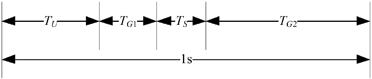
[0055] refer to figure 1 , the present invention provides an overall design of a timing signal, including the following:

[0056] (1) Keep the original BPM broadcast program and signal format unchanged;

[0057] (2) After the original coordinated time UTC and universal time UT1 signals end, the interval T G1 Insert described time service signal after the time, eliminate the influence to former BPM short-wave time service system user; The time interval T between the time service signal starting moment of described time service signal initial moment and original UTC time number and universal time UT1 time number end moment G1 Not less than 0.1s; the time interval T between the end time of the timing signal and the start time of the original coordinated time UTC time number and universal time UT1 time number G2 shall not be less than 0.1s, and T G2 ≥T G1 .

[0058] (3) The bandwidth of the timing signal must not exceed the available total bandwidth of the original BPM short-...

Embodiment 2

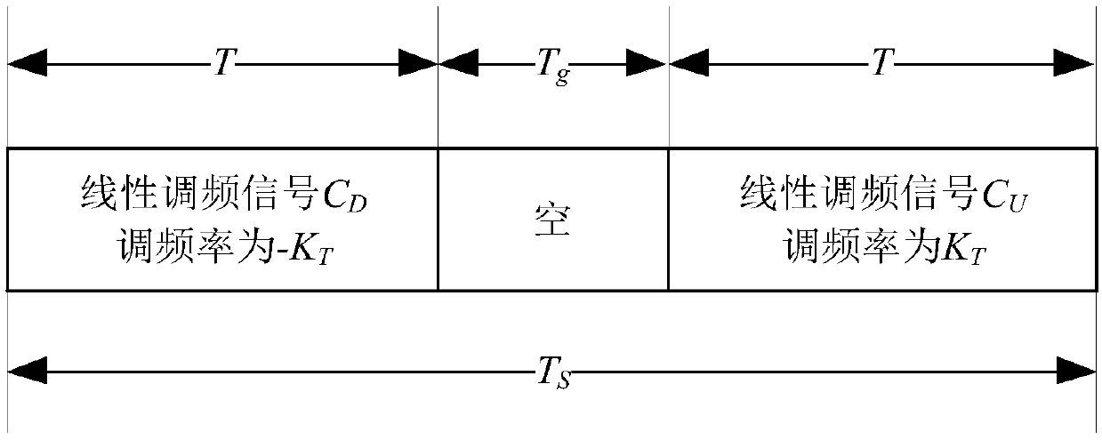
[0089] Utilize the present invention to design a kind of novel timing signal that is applicable and compatible with existing BPM short-wave timing system, and its time domain definition formula can be expressed as:

[0090]

[0091] In the formula:

[0092] (1) The initial time of the UTC time number of the original coordinated time and the UT1 time number of the universal time is the zero time of t;

[0093] (2)C sent (t) represents the time-domain definition formula of the timing signal; A is the signal amplitude, which is used for the transmitter to control the broadcast power; Re( ) represents the real part of the signal; j represents the imaginary unit; f 0 Indicates the carrier frequency, which can be 2.5MHz, 5MHz, 10MHz and 15MHz;

[0094] (3)C D (t)=exp[j(-Kπt2+πBt)], C U (t)=exp[j(-Kπt 2 +πBt)], where B=8000Hz, K=250000Hz / s;

[0095] (4)T a =0.4s; T b =0.432s; T c =0.448s; T d = 0.48s;

[0096] The beneficial effects brought by the above-mentioned design...


PUM


Abstract

The invention provides a BPM shortwave timing signal and timing method based on Chirp signals. A timing signal is obtained by combining two Chirp base band signals with zero central frequency and opposite frequency modulation numbers through a time division mode and modulating the carrier frequency, and the timing signal is used for realizing a timing function; a receiving terminal can obtain signal measurement precision higher than that of original BPM time signals and extra anti-interference gain and then obtain more reliable timing performance. The timing signal can be compatible in an original BPM shortwave timing system without affecting users of the original system in use; the timing signal has the advantages of high multi-path fading resistance, Doppler frequency shift resistance and the like and is particularly suitable for shortwave signal channels; frequency adjusting and timing can be realized for the timing signal through simple matching and filtering without a complicatedcarrier loop or code tracking loop.

Description

technical field [0001] The invention relates to the technical field of time service and information processing, in particular to a BPM short-wave time service signal and a timing method. Background technique [0002] As one of the large scientific devices, the BPM short-wave timing system is a long-range land-based radio timing service system independently mastered by my country. It has the advantages of long distance, simple receiving equipment, low price, and wartime persistence. The BPM short-wave time service system alternately broadcasts standard time and standard frequency signals at 4 frequencies (2.5MHz, 5MHz, 10MHz, 15MHz) every day. The content of the broadcast includes the UTC time number of the coordinated universal time, the UT1 time number of the universal time, empty carrier and BPM call sign. BPM timing broadcast program: (1) 59 m 00 s ~00 m 00 s and 29 m 00 s ~30 m 00 s Broadcast BPM callsign; (2)00 m 00 s ~10 m 00 s 、15 m 00 s ~25 m 00 s 、3...

Claims


Application Information

Patent Timeline
IPC IPC(8): G04R20/00
CPCG04R20/00
Inventor 袁江斌闫温合华宇李实锋胡召鹏高媛媛
Owner NAT TIME SERVICE CENT CHINESE ACAD OF SCI
Why Eureka
Try Eureka