Large-scale concrete mixing engine for irrigation works

A technology for mixing host and concrete, applied in cement mixing devices, clay preparation devices, unloading devices, etc., can solve the problem of low mixing volume per tank, reduce production management, ensure mixing quality, and reduce the number of mixing buildings. Effect

Pending Publication Date: 2018-07-31
SHANTUI JANEOO MACHINERY
View PDF0 Cites 1 Cited by
  • Summary
  • Abstract
  • Description
  • Claims
  • Application Information

AI Technical Summary

Problems solved by technology

[0005] The purpose of the present invention is to provide a hydraulic large-scale concrete mixing main engine, which is used to solve the problem of low mixing volume per tank in the prior art

Method used


Image

  • Large-scale concrete mixing engine for irrigation works
  • Large-scale concrete mixing engine for irrigation works
  • Large-scale concrete mixing engine for irrigation works

Examples


Embodiment approach 1

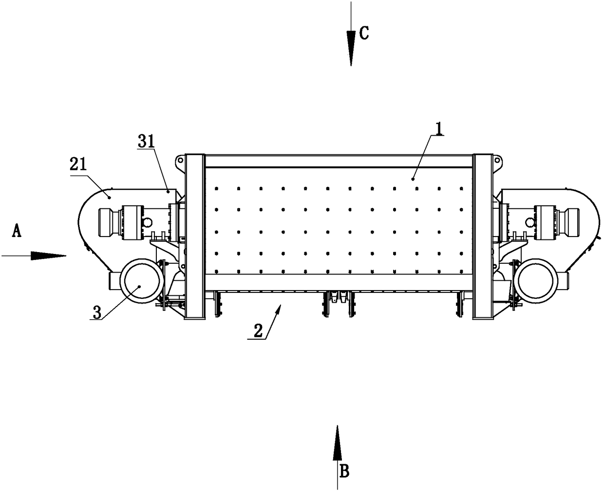
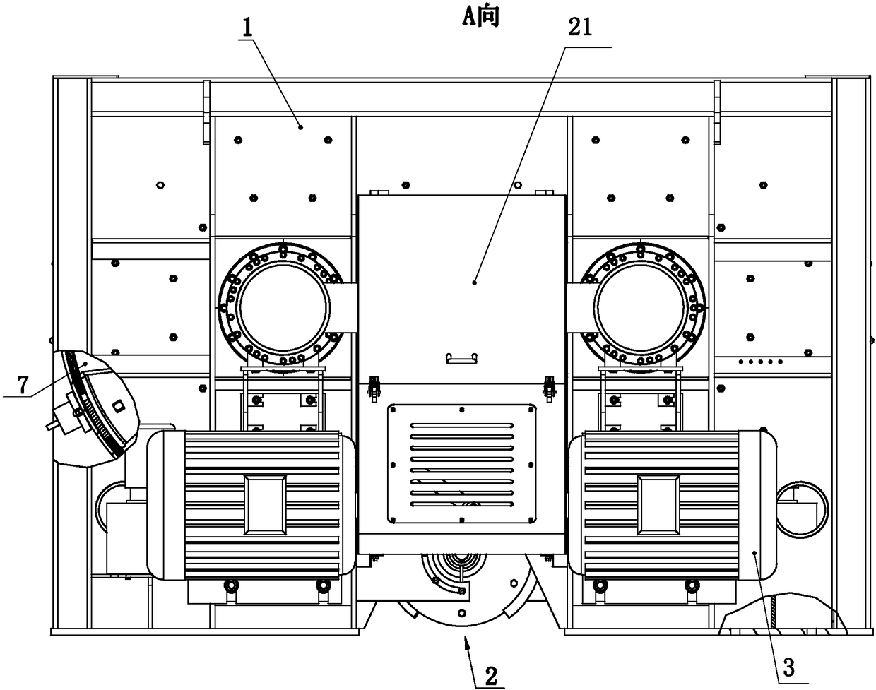
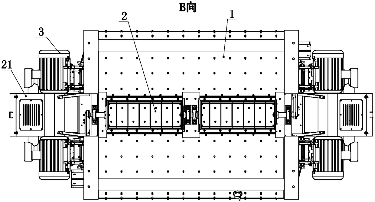
[0030] like Figure 1 to Figure 4 As shown, the present invention includes a stirring tank 1, a stirring device and a drive system. The bottom of the stirring tank 1 is provided with two discharge doors 2, and each discharge door 2 is connected to the stirring tank 1 in rotation, and each discharge door 2 Each transmission is connected with a hydraulic drive package for driving the discharge door 2 to rotate. The hydraulic drive package is provided with a cabinet 21 at both ends of the outside of the mixing tank 1, and the hydraulic drive package is arranged in the cabinet 21. The size of each discharge door 2 is the same, and the axis of rotation of each discharge door 2 on the mixing tank 1 is coaxially arranged. The stirring tank 1 is about 7 meters long, about 3.2 meters wide, and about 2.2 meters high. The stirring tank 1 is respectively provided with lining plates 11 for flow guiding at the positions of the discharge openings where the discharge doors 2 are located. Th...

Embodiment approach 2

[0039] like Figure 4 to Figure 7 As shown, the difference between the second embodiment and the first embodiment is that the structure of the stirring blade 6 is different, and the end of the stirring blade 6 near the rotating shaft 4 is defined as the inner end of the stirring blade 6, and the end of the stirring blade 6 away from the rotating shaft 4 is defined as The outer end of stirring blade 6.

[0040] The structure of the stirring blade in the present embodiment is as Figure 7 As shown, the long and wide surfaces of the stirring blade 6 are rectangular, and the outer end of the stirring blade is provided with a chute 61, and the length direction of the chute 61 extends along the side of the long and wide surface of the agitating blade at the outer end. In this embodiment, by setting the chute 6, the axial flow of the mixed material is strengthened, which is conducive to improving the mixing efficiency and mixing effect, that is, along the direction parallel to the a...


PUM

PropertyMeasurementUnit
particle diameteraaaaaaaaaa

Abstract

The invention relates to the technical field of concrete mixing, in particular to a large-scale concrete mixing engine for irrigation works. The large-scale concrete mixing engine is used for solvingthe problem that in the prior art, the single-tank mixing amount is small. The large-scale concrete mixing engine for the irrigation works comprises a mixing tank, a mixing device and a driving system. Two unloading doors are arranged at the bottom of the mixing tank, and the unloading doors are rotationally connected to the mixing tank. Each unloading door is in transmission connection with a hydraulic driver for driving the unloading door to rotate, and the mixing device is arranged in the mixing tank. The mixing device is in transmission connection with the driving system, and the driving system achieves double-end driving on the mixing device. The large-scale concrete mixing engine has the beneficial effects that the single-tank mixing amount can reach 9,000 L, and the large-scale concrete mixing engine is especially suitable for mixing work of roller compacted concrete for the irrigation works.

Description

technical field [0001] The invention relates to the technical field of concrete mixing, in particular to a hydraulic large-scale concrete mixing main engine. Background technique [0002] In recent years, with the vigorous promotion of concrete and the high efficiency, high quality and high benefit of engineering construction, it has effectively promoted the rapid improvement of concrete mixing equipment in terms of performance and technical level, and continues to expand to large development in the direction of globalization and multifunctionality. [0003] Since the aggregate particle size in hydraulic concrete such as roller compacted concrete is relatively large, and the quality of the concrete is high, the mixing volume per tank of the prior art concrete mixer is relatively low. The concrete mixer is located in the concrete mixing building, so this reduces the production capacity of the building, thereby increasing the demand for the site, and is not conducive to contr...

Claims


Application Information

Patent Timeline
Patent Type & Authority Applications(China)
IPC IPC(8): B28C5/14B28C7/16
CPCB28C5/14B28C7/16
Inventor 胡连花陈伟平张世同刘澍宏孙庆华
Owner SHANTUI JANEOO MACHINERY
Why Eureka
Try Eureka