Hydraulic bushing

A hydraulic bushing and sleeve technology, applied in the direction of shock absorbers, springs, spring/shock absorbers, etc., can solve the problems of increasing train operating costs, wear of wheels and tracks, etc., and achieve the effect of maintaining stable operation and high rigidity

Active Publication Date: 2018-07-31
ZHUZHOU TIMES RUIWEI ANTI VIBERATION EQUIP LTD
View PDF12 Cites 15 Cited by
  • Summary
  • Abstract
  • Description
  • Claims
  • Application Information

AI Technical Summary

Problems solved by technology

However, such a rubber arm with greater rigidity will cause severe wear and tear on the wheels and tracks in the curve driving state, thereby increasing the operating cost of the train

Method used


Image

  • Hydraulic bushing
  • Hydraulic bushing
  • Hydraulic bushing

Examples


Embodiment Construction

[0035] The present invention will be further described below in conjunction with accompanying drawing.

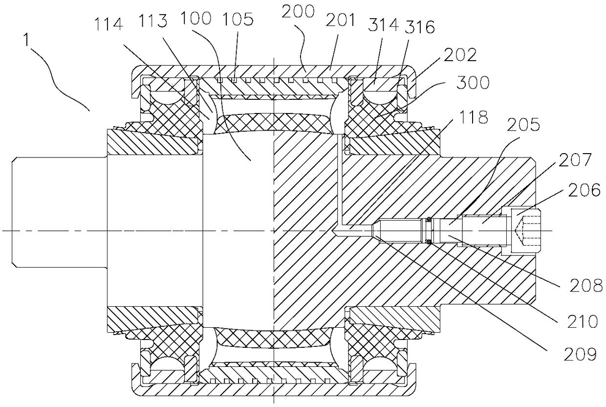
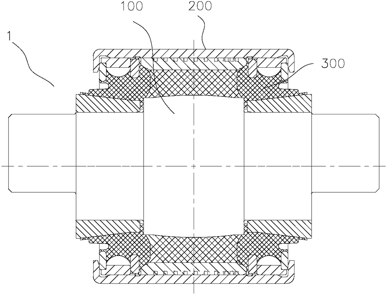
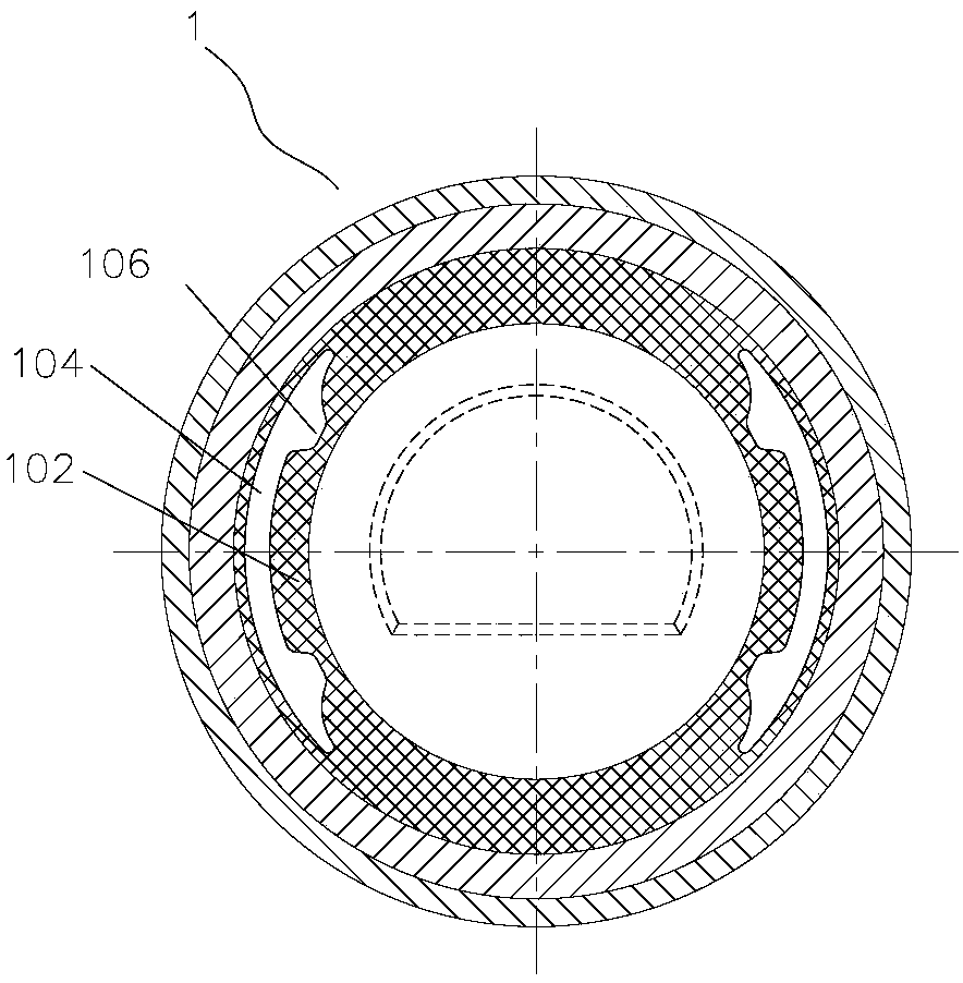
[0036] like Figure 1-3 As shown, the hydraulic bushing 1 includes a main spring 100 and a cylindrical casing 200 . like Figure 4-6 As shown, the main spring 100 has a mandrel 101 , a first rubber body 102 and a sleeve 103 . The first rubber body 102 is sheathed on the outer wall of the mandrel 101 . Two liquid chambers 104 are provided on the first rubber body 102 . In addition, in the radial direction of the first rubber body 102, two liquid cavities 104 are oppositely distributed at intervals. The sleeve 103 is sheathed on the outer wall of the first rubber body 102 . Meanwhile, a groove 110 is provided on the wall of the sleeve 103 . Wherein, the main spring 100 is disposed in the inner cavity of the casing 200 , so that the casing 200 and the sleeve 103 form a first flow channel 105 at the groove 110 for communicating with the two liquid chambers 104 .

[0037]...


PUM


Abstract

The invention relates to a hydraulic bushing which comprises a core shaft, a first rubber body, a sleeve, a jacket and sealing assemblies, wherein the core shaft is provided with a first stepped surface, so that the core shaft can be constructed as a stepped shaft of which the middle segment has a diameter greater than the two end parts; the first rubber body is arranged on the outer wall of the middle segment of the core shaft in a sleeving manner; two liquid cavities distributed in a spacing manner are arranged on the first rubber body; the sleeve is arranged on the outer wall of the first rubber body in a sleeving manner; a groove is formed in the outer wall of the sleeve; the jacket is arranged on the outer side of the sleeve in a sleeving manner; a first passageway used for communicating with the two liquid cavities is formed by adopting the jacket and the sleeve in the groove; and the sealing assemblies are arranged at two ends of the core shaft, and are in sealing contact with the first stepped surface and end surfaces of the sleeve. The hydraulic bushing is conducive to the stable traveling of a rail train, and the abrasion to train wheels and rails in the curve traveling state can be reduced.

Description

technical field [0001] The invention relates to the technical field of rail trains, in particular to a hydraulic bushing. Background technique [0002] The operation of rail trains can be simply divided into two states, the first is a straight state, and the second is a curved state. In the prior art, the wheels are usually connected to the bogie by means of rubber pivot arms, so that the train can run quickly and stably along the rails in a straight-ahead state; and the train can turn smoothly along the track in a curved state. [0003] In order to make the train run stably in the straight running state, the rubber rotating arm is usually constructed to have a larger rigidity value. However, such a rubber arm with relatively high rigidity will cause severe wear of the wheels and tracks in the curve driving state, thereby increasing the operating cost of the train. Contents of the invention [0004] To address part or all of the above problems, the present invention prop...

Claims


Application Information

Patent Timeline
Patent Type & Authority Applications(China)
IPC IPC(8): F16F13/14B61F5/42
CPCB61F5/42F16F13/14
Inventor 罗俊冯万盛蒋仲三荣继刚邹波黄江彪肖祥龙
Owner ZHUZHOU TIMES RUIWEI ANTI VIBERATION EQUIP LTD
Why Eureka
Try Eureka