Vehicle headlight

A vehicle, sub-light technology, applied in the direction of headlights, road vehicles, vehicle components, etc., can solve problems such as unsatisfactory application and brightness limitations

Active Publication Date: 2018-07-31
ZKW GRP GMBH
View PDF8 Cites 4 Cited by
  • Summary
  • Abstract
  • Description
  • Claims
  • Application Information

AI Technical Summary

Problems solved by technology

However, the disadvantage is that the light image is very limited with regard to its geometry, that is to say with respect to the ratio of width to height in the projection ahead of the vehicle, but also with regard to the brightness to be achieved and therefore the The DLP® technology described is not ideal for all light functions, e.g. in cornering light functions

Method used


Image

  • Vehicle headlight
  • Vehicle headlight
  • Vehicle headlight

Examples


Embodiment Construction

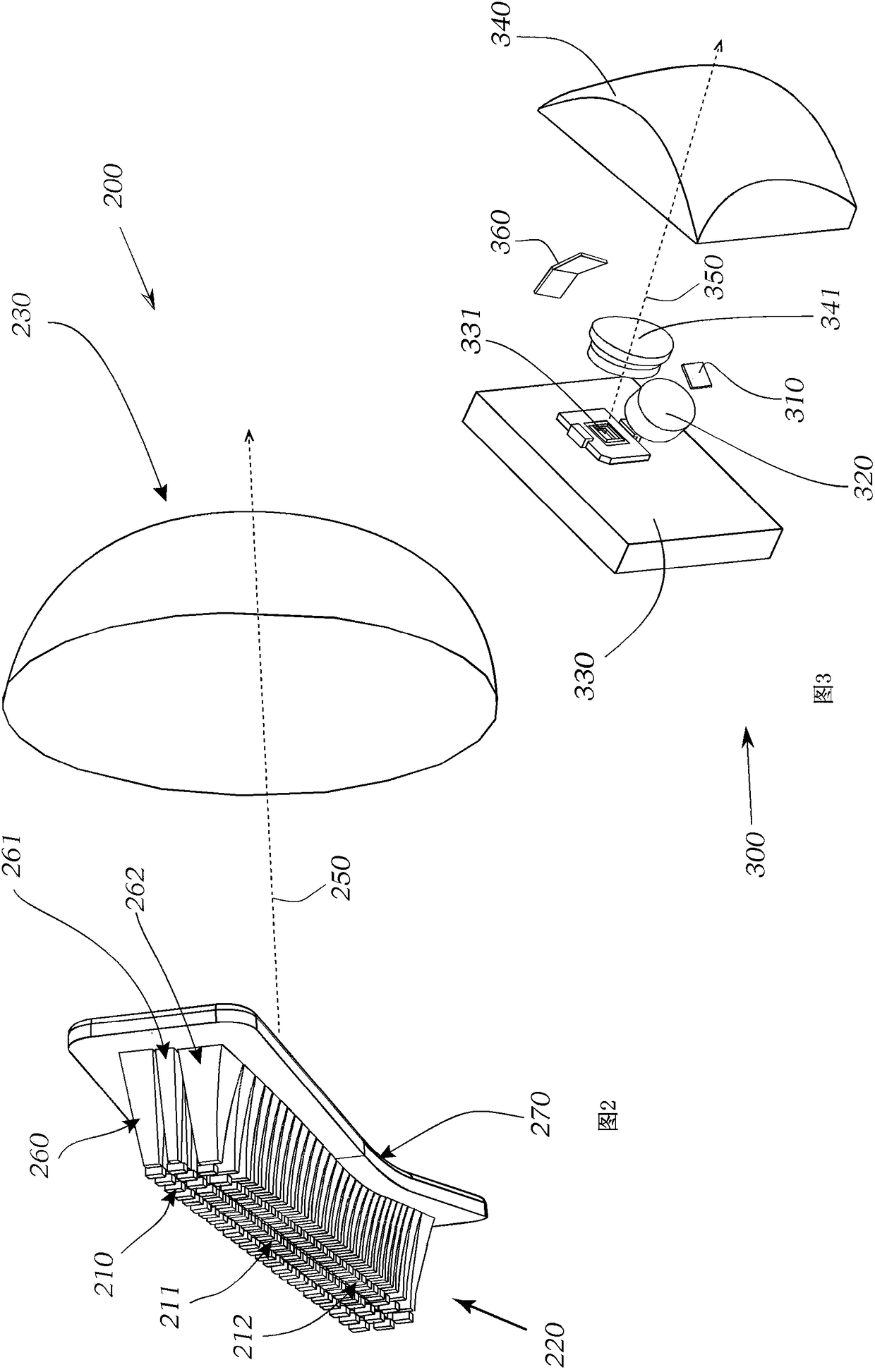
[0109] Now, refer to Figure 1 to Figure 12 Examples of the present invention are explained in more detail. In particular, the relevant components in the headlight are shown for the present invention, wherein it is clear that the headlight also contains many other, not shown components, which are implemented in a motor vehicle, such as in particular a PKW or a motorcycle. meaningful use in . For the sake of clarity, cooling devices for structural components, control electronics, further optical elements, mechanical adjustment mechanisms or holders, for example, are therefore not shown.

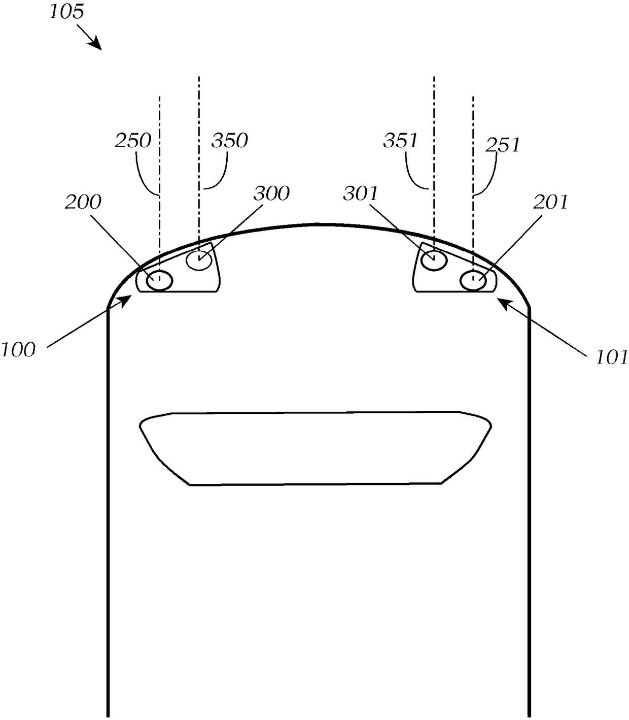
[0110] exist figure 1 201 , 301 , a vehicle 105 is shown in a view from above with two vehicle headlights 100 , 101 , which respectively comprise two light modules 200 , 300 ; 201 , 301 .

[0111] In the state in which the headlights 100, 101 have been installed in the vehicle 105, the first radiation direction 250, 251 of the first light image and the second radiation direction 350, 351 of...


PUM


Abstract

The invention relates to a vehicle headlignt comprising at least two light modules, wherein a first light module is arranged to generate a dynamically controllable first partial light distribution (510). The first light module comprises at least a first light source and at least a first device for generating a first light-emitting image from the first partial light distribution (510) and at leasta first projection optical mechanism, wherein by means of the at least one first projection optical mechanism, the first light-emitting image can be used as a first light image to be projected onto the street in a first emission direction. A second light module is arranged to generate a dynamically controllable second partial light distribution (520). The second light module comprises at least onesecond light source and at least one second device for generating a second light-emitting image from the second partial light distribution (520) and at least one second projection optical mechanism.

Description

technical field [0001] The invention relates to a vehicle headlight comprising at least two light modules. Background technique [0002] In the development of current headlight systems, the desire to be able to project onto the roadway a light image with the highest possible resolution, which can change rapidly and which is compatible with the corresponding traffic, road and light, is increasingly at the center of attention. conditions match. The term "roadway" is used here for simplified presentation, since whether the light image actually lies on the roadway or extends beyond it obviously depends on the local facts. In principle, the light image in the sense used here is defined by its projection onto a vertical plane which corresponds to the relevant standards concerning lighting technology for motor vehicles. The resulting light image should also be adaptable to different traffic situations. [0003] In order to respond to this mentioned requirement, in particular hea...

Claims


Application Information

Patent Timeline
Patent Type & Authority Applications(China)
IPC IPC(8): F21S41/24F21S41/30F21W102/13F21W107/10
CPCF21S41/24F21S41/30F21W2107/10F21W2102/13F21S41/255F21S41/663F21S41/675F21S41/143F21S41/153
Inventor M.拉梅
Owner ZKW GRP GMBH
Why Eureka
Try Eureka