Supercharge Your Innovation With Domain-Expert AI Agents!

Base for power cabinet and with cleaning function

A power cabinet and cleaning technology, applied in the direction of cleaning methods using tools, cleaning methods and utensils, chemical instruments and methods, etc., can solve the problems of low dust removal efficiency and poor dust removal effect, and achieve high dust removal efficiency and good dust removal effect Effect

Inactive Publication Date: 2018-08-03
胡叙成
View PDF9 Cites 1 Cited by
  • Summary
  • Abstract
  • Description
  • Claims
  • Application Information

AI Technical Summary

Problems solved by technology

[0005] In order to overcome the shortcomings of poor dust removal effect and low dust removal efficiency during manual dust removal, the technical problem to be solved by the invention is to provide a base with cleaning function for power cabinets with better dust removal effect and high dust removal efficiency

Method used


Image

  • Base for power cabinet and with cleaning function
  • Base for power cabinet and with cleaning function
  • Base for power cabinet and with cleaning function

Examples


Embodiment 1

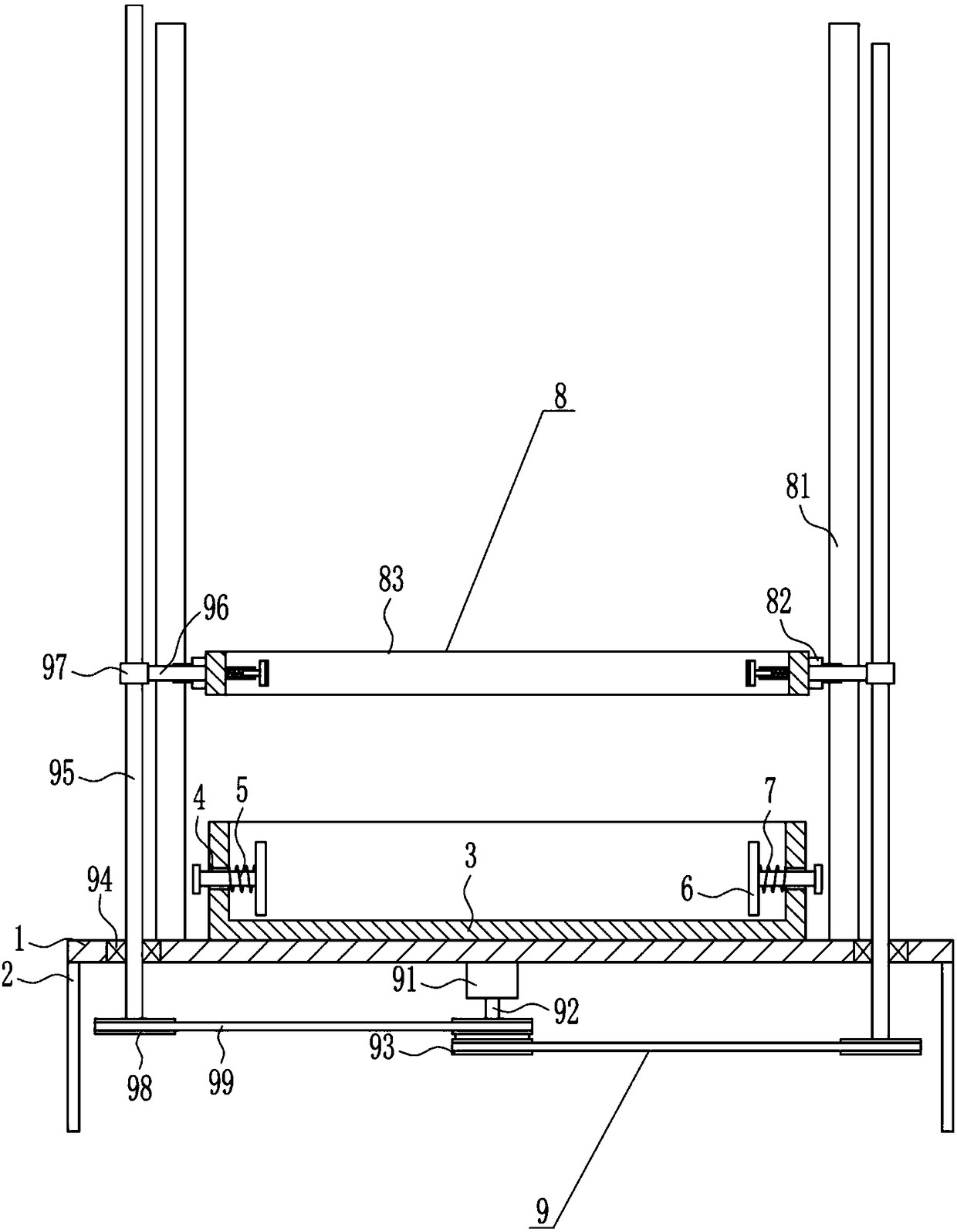
[0029] A base with a cleaning function for a power cabinet, such as Figure 1-5 As shown, it includes a mounting plate 1, a pole 2, a frame body 3, a T-shaped bar 5, a rubber plate 6, a first spring 7, a cleaning device 8 and a driving device 9, and the four corners of the bottom of the mounting plate 1 are provided with poles 2. A frame body 3 is installed in the middle of the top of the mounting plate 1. Guide holes 4 are opened on the left and right sides of the frame body 3. T-shaped rods 5 are slidingly installed in the guide holes 4, and rubber is installed on the inner ends of the T-shaped rods 5. Plate 6, the first spring 7 is connected between the outer side of the rubber plate 6 and the inner side of the frame body 3, the first spring 7 is wound on the T-shaped bar 5, a cleaning device 8 is provided on the mounting plate 1, and a drive is provided at the bottom of the mounting plate 1 device9.

Embodiment 2

[0031] A base with a cleaning function for a power cabinet, such as Figure 1-5As shown, it includes a mounting plate 1, a pole 2, a frame body 3, a T-shaped bar 5, a rubber plate 6, a first spring 7, a cleaning device 8 and a driving device 9, and the four corners of the bottom of the mounting plate 1 are provided with poles 2. A frame body 3 is installed in the middle of the top of the mounting plate 1. Guide holes 4 are opened on the left and right sides of the frame body 3. T-shaped rods 5 are slidingly installed in the guide holes 4, and rubber is installed on the inner ends of the T-shaped rods 5. Plate 6, the first spring 7 is connected between the outer side of the rubber plate 6 and the inner side of the frame body 3, the first spring 7 is wound on the T-shaped bar 5, a cleaning device 8 is provided on the mounting plate 1, and a drive is provided at the bottom of the mounting plate 1 device9.

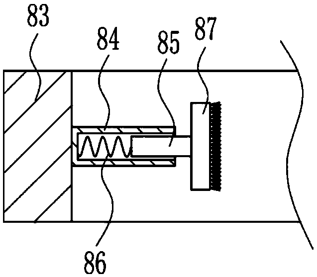
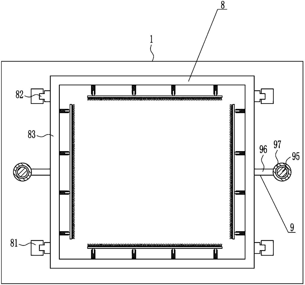
[0032] The cleaning device 8 includes a first slide rail 81, a first sli...

Embodiment 3

[0034] A base with a cleaning function for a power cabinet, such as Figure 1-5 As shown, it includes a mounting plate 1, a pole 2, a frame body 3, a T-shaped bar 5, a rubber plate 6, a first spring 7, a cleaning device 8 and a driving device 9, and the four corners of the bottom of the mounting plate 1 are provided with poles 2. A frame body 3 is installed in the middle of the top of the mounting plate 1. Guide holes 4 are opened on the left and right sides of the frame body 3. T-shaped rods 5 are slidingly installed in the guide holes 4, and rubber is installed on the inner ends of the T-shaped rods 5. Plate 6, the first spring 7 is connected between the outer side of the rubber plate 6 and the inner side of the frame body 3, the first spring 7 is wound on the T-shaped bar 5, a cleaning device 8 is provided on the mounting plate 1, and a drive is provided at the bottom of the mounting plate 1 device9.

[0035] The cleaning device 8 includes a first slide rail 81, a first sl...


PUM


Abstract

The invention relates to a power cabinet base, in particular to a base for a power cabinet and with a cleaning function. According to the base for the power cabinet and with the cleaning function, thededusting effect is good, and the dedusting efficiency is high. The base for the power cabinet and with the cleaning function comprises a mounting plate, supporting rods, a frame body, T-shaped rods,rubber plates, first springs and the like. The supporting rods are arranged at the four corners of the bottom of the mounting plate correspondingly, and the frame body is mounted in the middle of thetop of the mounting plate. Guiding holes are formed in the left portion and the right portion of the frame body correspondingly, and the T-shaped rods are slidably arranged in the guiding holes correspondingly. The rubber plates are mounted at the inner ends of the T-shaped rods correspondingly, and the first springs are connected between the outer sides of the rubber plates and the inner side ofthe frame body and wound on the T-shaped rods. The power cabinet is cleaned through a cleaning device, the cleaning device is driven through a driving device, and thus the effects of good dedusting effect and high dedusting efficiency are achieved.

Description

technical field [0001] The invention relates to a base of an electric cabinet, in particular to a base with a cleaning function for an electric cabinet. Background technique [0002] Power cabinets are mostly used to load instruments, meters, electronics, communications, automation, sensors, smart cards, industrial control, precision machinery and other items, and their materials are mostly high-quality aluminum alloy profiles. Aluminum alloy profiles have firm structure, beautiful appearance, and good heat dissipation And other characteristics, it is an ideal box for high-end instruments. [0003] After the power cabinet has been placed for a long time, dust will remain on its surface, and the dust removal effect is poor and the dust removal efficiency is low when the dust is removed manually. Therefore, it is urgent to develop a power cabinet with better dust removal effect and high dust removal efficiency. base. Contents of the invention [0004] (1) Technical problem...

Claims


Application Information

Patent Timeline
Patent Type & Authority Applications(China)
IPC IPC(8): B08B1/00B08B13/00F16H37/12
CPCF16H37/12B08B13/00B08B1/30B08B1/12
Inventor 胡叙成王培秀卓少莲
Owner 胡叙成
Features
  • R&D
  • Intellectual Property
  • Life Sciences
  • Materials
  • Tech Scout
  • Unparalleled Data Quality
  • Higher Quality Content
  • 60% Fewer Hallucinations
Learn More