
Charging mechanism of automatic magnetic shoe deburring device

A deburring and automatic technology, applied in the direction of grinding feed movement, grinding machine parts, metal processing equipment, etc., can solve the problems of time-consuming and labor-intensive manual loading, burrs on the end of magnetic tiles, work-related accidents, etc.

Inactive Publication Date: 2018-08-03
ANHUI NORMAL UNIV
View PDF6 Cites 9 Cited by
  • Summary
  • Abstract
  • Description
  • Claims
  • Application Information

AI Technical Summary

Problems solved by technology

[0002] In the production process of magnetic tiles, according to different production requirements, it is necessary to remove the burrs at the end of the magnetic tiles. In the traditional feeding method, because the cross section of the magnetic tiles is arc-shaped, it is difficult for the traditional manipulator to clean the magnetic tiles. For clamping and loading, the magnetic tiles are manually moved to the area to be processed. Because there are burrs on the end of the magnetic tiles, if you don’t pay attention, you will bruise your hands, causing work-related injuries, and manual loading is time-consuming and laborious. Working long hours also brings greater labor intensity to workers

Method used


Image

  • Charging mechanism of automatic magnetic shoe deburring device
  • Charging mechanism of automatic magnetic shoe deburring device
  • Charging mechanism of automatic magnetic shoe deburring device

Examples


Embodiment Construction

[0028] Below in conjunction with accompanying drawing and embodiment of description, specific embodiment of the present invention is described in further detail:

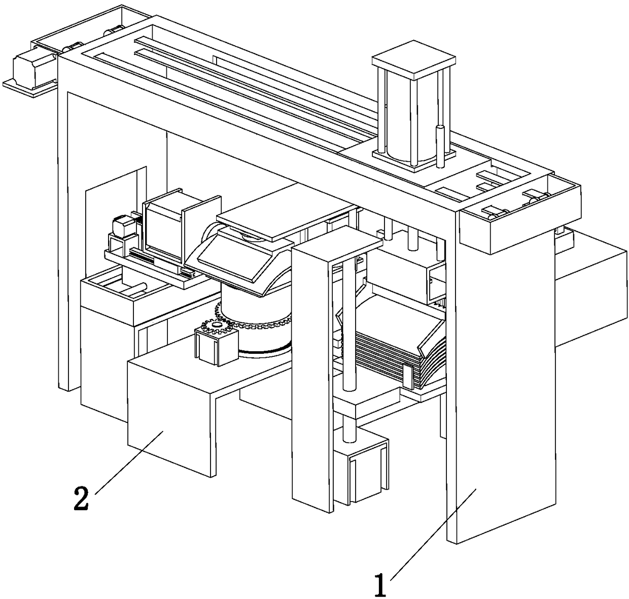
[0029] refer to Figure 1 to Figure 12 The shown automatic deburring device for magnetic tiles includes a feeding mechanism 1 for loading workpieces and a deburring mechanism 2 for deburring workpieces. The feeding mechanism 1 is located in the deburring mechanism 2 On the side, the deburring mechanism 2 includes a deburring assembly 3, a rotating assembly 4 for driving the workpiece to rotate, and a limit assembly 5 for limiting the workpiece. The rotating assembly 4 is located between the deburring assembly 3 and Between the feeding mechanism 1, the limit assembly 5 is located at the side of the rotating assembly 4, and the deburring assembly 3 includes a fixed frame 3a, a drive motor 3a1 and a material moving plate 3a2 above the fixed frame 3a, the material moving plate A U-shaped support plate 3a3 for installin...


PUM


Abstract

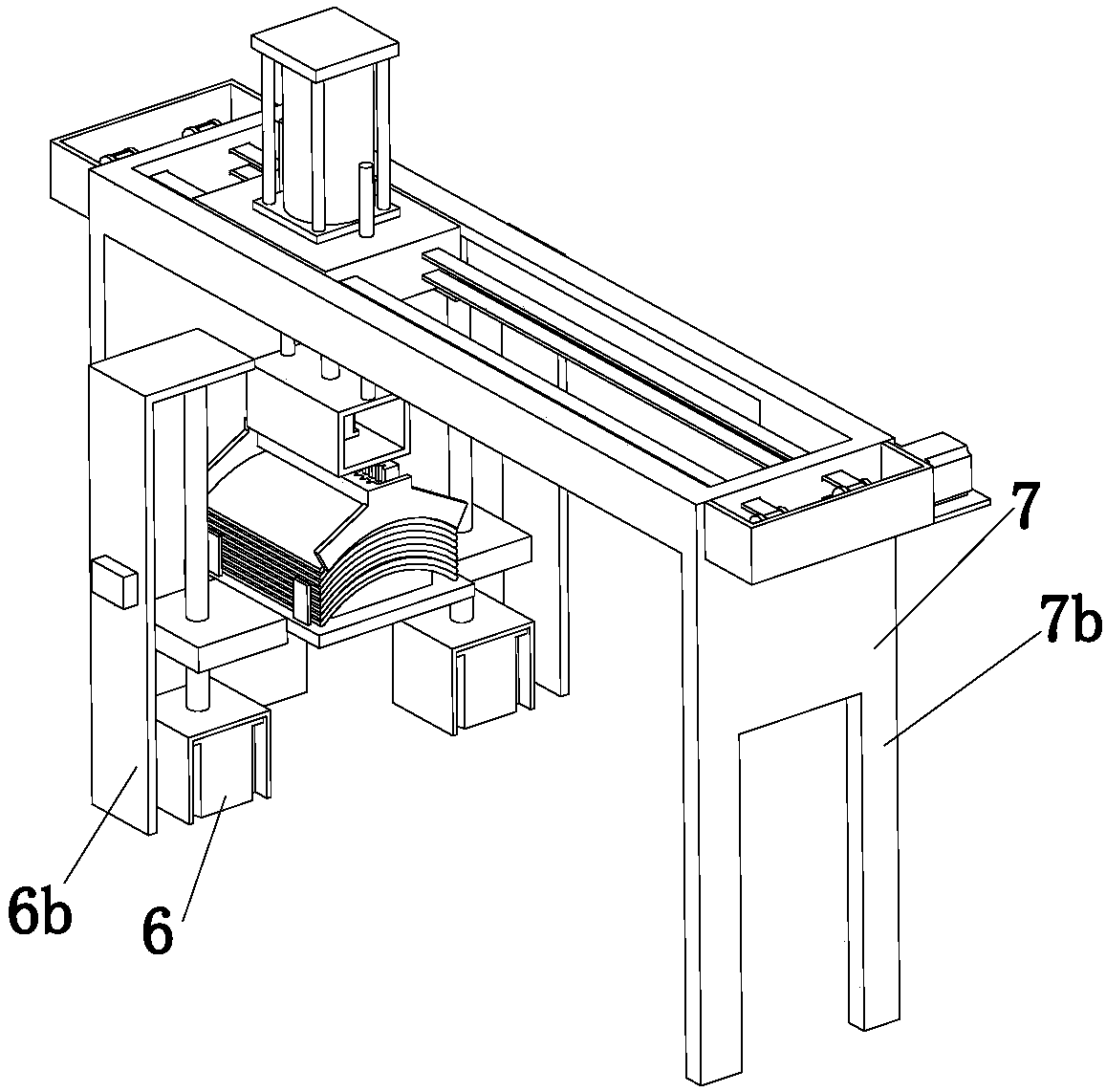
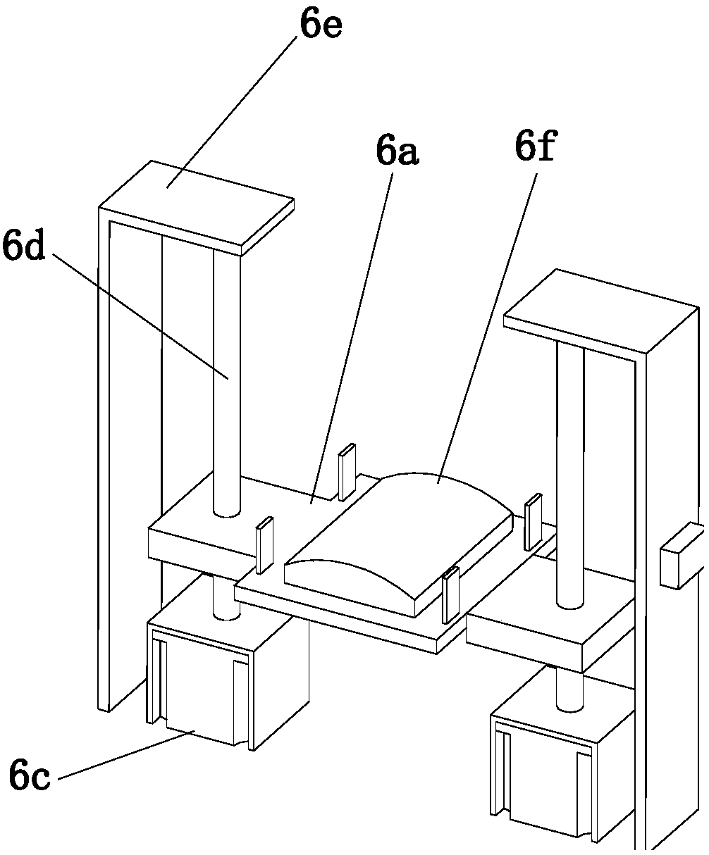
The invention relates to the technical field of machining, in particular to a charging mechanism of an automatic magnetic shoe deburring device. The charging mechanism comprises a material lifting assembly, a charging assembly and a material taking assembly. The material taking assembly and the charging assembly are located above the material lifting assembly. The charging assembly comprises a sliding block of a cuboid structure, and a bearing assembly used for supporting the sliding block. The bearing assembly comprises a mounting frame and two supporting plates which are located at the bottom of the mounting frame and used for supporting the bottom of the mounting frame. The sliding block is located in the mounting frame and is in sliding fit with the mounting frame. The material takingassembly comprises a lifting assembly located at the top of the sliding block, and a clamping assembly located below the sliding block. Workpieces can be automatically moved to a machining waiting area, the production efficiency of enterprises is improved, the labor intensity of workers is relieved, in addition, the workpieces can be clamped through the material taking assembly, and industrial accidents caused by manual charging by the workers are avoided.

Description

technical field [0001] The invention relates to the technical field of mechanical processing, in particular to a feeding mechanism of a magnetic tile automatic deburring device. Background technique [0002] In the production process of magnetic tiles, according to different production requirements, it is necessary to remove the burrs at the end of the magnetic tiles. In the traditional feeding method, because the cross section of the magnetic tiles is arc-shaped, it is difficult for the traditional manipulator to clean the magnetic tiles. For clamping and loading, the magnetic tiles are manually moved to the area to be processed. Because there are burrs on the end of the magnetic tiles, if you don’t pay attention, you will bruise your hands, causing work-related injuries, and manual loading is time-consuming and laborious. Working long hours also brings greater labor intensity to workers. Contents of the invention [0003] The object of the present invention is to provid...

Claims


Application Information

Patent Timeline
Patent Type & Authority Applications(China)
IPC IPC(8): B24B41/00
CPCB24B41/005
Inventor 吴长义李琦琦许晨晨宋凤楼
Owner ANHUI NORMAL UNIV
Learn More