Crane Handling System for Cement Rotary Kiln

A cement rotary kiln and processing system technology, applied in rotary drum furnaces, furnaces, furnace types, etc., can solve problems such as errors, seriousness, and inability to accurately locate the shape of garbage at the driving position, and achieve the effect of reducing positioning errors.

Inactive Publication Date: 2019-07-09
温现国
View PDF6 Cites 0 Cited by
  • Summary
  • Abstract
  • Description
  • Claims
  • Application Information

AI Technical Summary

Problems solved by technology

[0006] The present invention aims at the problem that in the existing driving operation system, the driving position cannot be accurately positioned and the garbage shape is not fixed, and the error is extremely serious when using a conventional weighing device to weigh, and provides a driving processing system for cement rotary kiln

Method used


Image

  • Crane Handling System for Cement Rotary Kiln
  • Crane Handling System for Cement Rotary Kiln
  • Crane Handling System for Cement Rotary Kiln

Examples


Embodiment 1

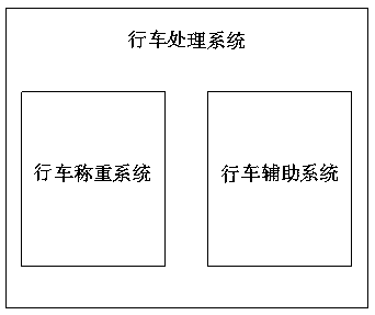
[0037] like figure 1 As shown, the driving handling system for cement rotary kiln includes the driving weighing system used to solve the driving weighing and the driving auxiliary system used to solve the driving positioning.

[0038] In use, the actual position of the vehicle can be determined through multiple positioning devices, which greatly reduces the positioning error and achieves the effect of auxiliary positioning. At the same time, based on the weighing system, the grab can obtain the weight of the garbage it grabs every time it grabs. .

Embodiment 2

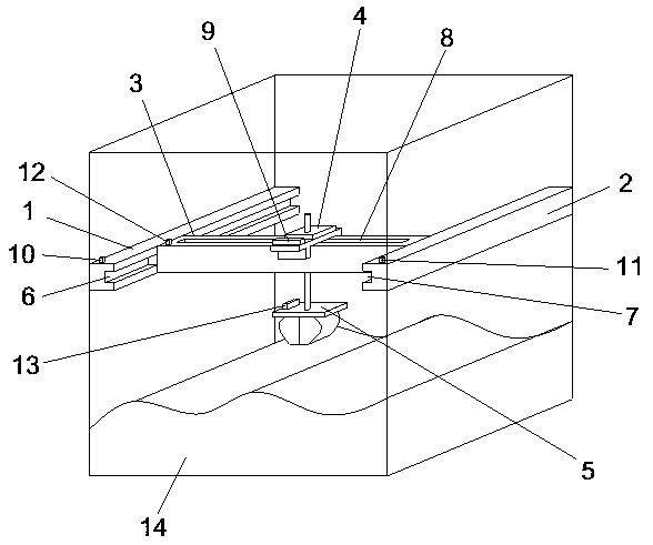
[0040] Based on Example 1, such as figure 2 As shown, the driving assistance system includes a first beam 1, a second beam 2, a movable beam 3, a driving 4 and a grab bucket 5, the first beam 1 is set opposite to the second beam 2, and the first beam 1 is provided with a first guide rail 6. The second beam 2 is provided with a second guide rail 7, the two ends of the movable beam 3 are respectively arranged in the first guide rail 6 and the second guide rail 7, and the movable beam 3 is provided with a third guide rail 8, and the driving 4 and the movable beam 3 It is movably connected and connected with the grab bucket 5 through the lifting rod passing through the third guide rail 8. The first beam 1 is provided with a first fixed positioning device 10, and the second beam 2 is provided with a second fixed positioning device 11. The movable beam 3 is provided with a first mobile positioning device 12, the driving 4 is provided with a second mobile positioning device 9, the g...

Embodiment 3

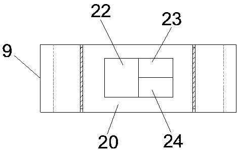
[0043] Based on Example 2, such as image 3 As shown, the second mobile positioning device 9 is provided with a working chamber 20 , and the working chamber 20 is provided with a wireless communication module 22 , a power supply 23 and a control module 24 electrically connected to each other.

[0044] In use, the wireless communication modules in the first fixed positioning device, the second fixed positioning device, the first mobile positioning device, the second mobile positioning device and the third mobile positioning device are close to each other.


PUM


Abstract

The invention relates to the technical field of garbage recycling, in particular to a travelling crane processing system for a rotary cement kiln. The travelling crane processing system comprises a travelling crane weighing system and a travelling crane auxiliary system, wherein the travelling crane weighing system comprises a base, a lifting rod, a weighing device, a thrust bearing and a grab bucket; the lower part of the base is connected with the grab bucket; a through hole is formed in the center of the base; the upper part of the base is connected with the weighing device; the thrust bearing is arranged above the weighing device; the travelling crane auxiliary system comprises a first cross beam, a second cross beam, a movable beam, a travelling crane and the grab bucket; a first fixed positioning device is arranged on the first cross beam; a second fixed positioning device is arranged on the second cross beam; a first movable positioning device is arranged on the movable beam; asecond movable positioning device is arranged on the travelling crane; and a third movable positioning device is arranged on the grab bucket. The travelling crane processing system solves the problemsthat the position of the travelling crane cannot be precisely positioned in the existing travelling crane operating system and the error is extremely serious when the conventional weighing device isadopted to weigh garbage as the form of the garbage is not fixed.

Description

technical field [0001] The invention relates to the field of garbage recovery, in particular to a driving processing system for a cement rotary kiln. Background technique [0002] Cement is a powdery hydraulic inorganic gelling material. After adding water and stirring, it becomes a slurry, which can be hardened in the air or better hardened in water, and can firmly bind sand, stone and other materials together. [0003] In order to realize the reduction, resource utilization and harmless treatment of urban domestic waste, explore a new way of urban domestic waste treatment, reuse waste, and absorb urban domestic waste based on cement rotary kiln, so that the heat generated by its combustion can be used in cement production. [0004] In use, it is necessary to locate the driving position so that the operator can accurately control the driving to the designated position. At the same time, the driving position can be positioned and the entire material transfer step can be au...

Claims


Application Information

Patent Timeline
Patent Type & Authority Patents(China)
IPC IPC(8): F27B7/32
CPCF27B7/3205
Inventor 温现国谢百钰郭明全
Owner 温现国
Why Eureka
Try Eureka