
In-situ lateral earth pressure measuring device and method

A lateral earth pressure, measuring device technology, applied in measuring devices, force/torque/work measuring instruments, instruments, etc., can solve the problems of affecting the measurement accuracy, instability of the measurement position, non-recovery, etc., and achieve a high degree of automatic control. , high numerical accuracy, cleverly designed effects

Active Publication Date: 2018-08-03
SHANDONG UNIV OF TECH
View PDF6 Cites 7 Cited by
  • Summary
  • Abstract
  • Description
  • Claims
  • Application Information

AI Technical Summary

Problems solved by technology

[0004] 1. After the pressure box is buried in the soil, it is generally not recyclable, and there is a serious waste;
[0005] 2. When measuring the lateral earth pressure, the pressure cell needs to be buried in the soil through special installation and fixing equipment, so that the measurement surface can correctly contact the soil. However, due to the backfill or excessive disturbance of the soil, the measurement position is unstable and serious. Affect the measurement accuracy;
[0006] 3. Although the backfill soil after soil drilling is mostly configured according to the original soil properties, it is still not the original soil layer. In addition, the pressure relief and disturbance of the soil after backfilling soil, the accuracy of the measured lateral earth pressure is not high

Method used


Image

  • In-situ lateral earth pressure measuring device and method
  • In-situ lateral earth pressure measuring device and method
  • In-situ lateral earth pressure measuring device and method

Examples


Embodiment Construction

[0029] It should be pointed out that the following detailed description is exemplary and intended to provide further explanation to the present application. Unless defined otherwise, all technical and scientific terms used herein have the same meaning as commonly understood by one of ordinary skill in the art to which this application belongs.

[0030] It should be noted that the terminology used here is only for describing specific implementations, and is not intended to limit the exemplary implementations according to the present application. As used herein, unless the context clearly dictates otherwise, the singular is intended to include the plural, and it should also be understood that when the terms "comprising" and / or "comprising" are used in this specification, they mean There are features, steps, operations, means, components and / or combinations thereof.

[0031] As introduced in the background technology, most of the existing measurement methods are pre-embedded pre...


PUM


Abstract

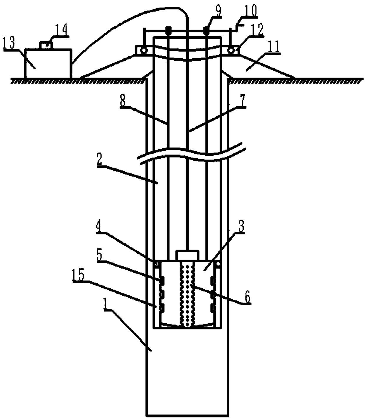
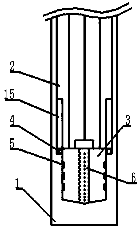
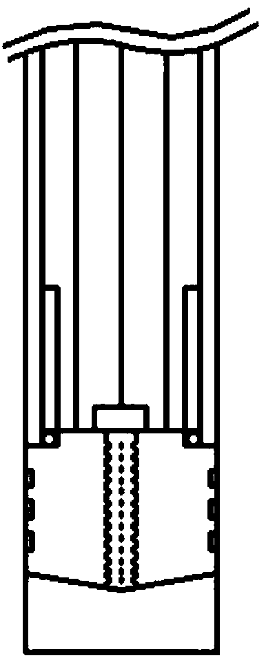
The invention discloses an in-situ lateral earth pressure measuring device and method. The device comprises a measuring part and a control part. The measuring part comprises a measuring tube and an air bag. The top of the measuring tube is positioned by an adjustable clamp in order that the measuring tube and a measuring hole are coaxial. A guide rail is arranged on the inner sidewall of the lowerend of the measuring tube. A plurality of electromagnetic balls are distributed in the circumferential direction of the top of the air bag and can slide along the guide rail at the lower end of the measuring tube. An air guiding device is disposed at the center of the air bag. The upper interface of the air guiding device is connected to an air guiding tube. The air guiding tube extends out of the measuring tube to uniformly fill the air bag with air. A plurality of strain sensors are distributed on the sidewall of the air bag. The control part comprises a control box and a gas storage tank.The control box controls the amount of air introduced into the air bag by the air storage tank so as to calculate the expansion volume of the air bag. The controller receives the feedback signals of the strain sensors to show a stress and strain value relation curve of the lateral earth pressure. The air storage tank is connected to the air guiding tube and is the air source of the entire measuring device.

Description

technical field [0001] The invention relates to an in-situ earth pressure measuring device, in particular to a lateral earth pressure measuring device and a measuring method. Background technique [0002] In engineering design and safety assessment, the earth pressure of the interaction between soil and structure is a crucial factor. Most of the earth pressure measurement is vertical pressure measurement, but the measurement of lateral earth pressure is relatively difficult, and special measuring devices need to be designed for measurement. [0003] Most of the existing measurement methods are pre-embedded pressure cells by drilling, then filling the same or similar soil and compacting to measure the soil pressure, and the measurement of lateral earth pressure requires the design of special pressure cell installation equipment to obtain relatively accurate value. The existing method has the following defects: [0004] 1. After the pressure box is buried in the soil, it is...

Claims


Application Information

Patent Timeline
Patent Type & Authority Applications(China)
IPC IPC(8): G01L5/00
CPCG01L5/00
Inventor 史萍刘建平
Owner SHANDONG UNIV OF TECH
Learn More