Improved air dust removing device

An improved technology for air dust removal, which is applied in the direction of coupling devices, parts of connecting devices, and connecting/disconnecting devices. Small potential safety hazards, the effect of improving the safety of electricity use

Inactive Publication Date: 2018-08-03
广州诗琬家居有限公司
View PDF3 Cites 0 Cited by
  • Summary
  • Abstract
  • Description
  • Claims
  • Application Information

AI Technical Summary

Problems solved by technology

[0002] Air dust collectors are widely used in industrial production. They are mainly used for adsorption and dust removal of polluted gases generated during industrial production. However, due to the high power of these dust collectors, some factories are specially equipped with plug-in power supply for dust collectors. Power distribution cabinets, however, these power distribution cabinets have a single setting mode, and the internal conductive sheets are set relatively outside. This conductive sheet is easily touched by metal sheets or metal rods. Therefore, when people who lack safety awareness use metal sheets Or electric shock accidents are likely to occur when the rod is in contact with the conductive sheet; at the same time, the dust collector needs to move its position frequently during the dust removal operation, so that it is easy to be affected by the pulling of the power supply line and cause the plug to loosen, resulting in interruption of power supply. It brings great inconvenience. In addition, most of the existing power distribution cabinets are fixed on the ground, which makes the occupied area larger. In some special cases, due to the limitation of the length of the power supply line, if the power distribution cabinet cannot be moved. Unable to complete power connection, severely impacting dust extraction operations

Method used


Image

  • Improved air dust removing device
  • Improved air dust removing device
  • Improved air dust removing device

Examples


Embodiment Construction

[0027] All features disclosed in this specification, or steps in all methods or processes disclosed, may be combined in any manner, except for mutually exclusive features and / or steps.

[0028] Any feature disclosed in this specification (including any appended claims, abstract and drawings), unless expressly stated otherwise, may be replaced by alternative features which are equivalent or serve a similar purpose. That is, unless expressly stated otherwise, each feature is one example only of a series of equivalent or similar features.

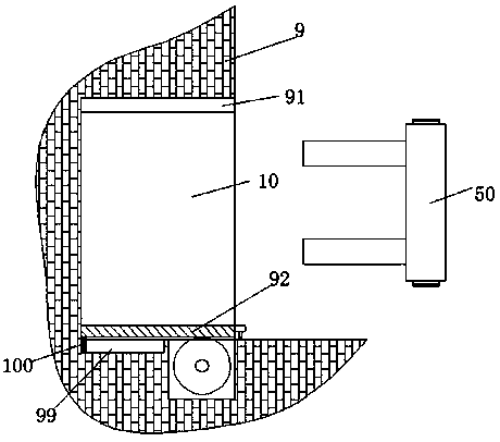
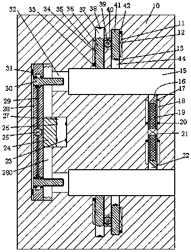
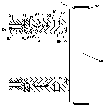
[0029] Such as Figure 1 to Figure 5 As shown, an improved air dust removal device of the device of the present invention includes an accommodating cavity 91 with an opening facing the right in the wall 9, a power distribution cabinet 10 set in the accommodating cavity 91 through a push assembly, and a dust remover Electrically connected plug head 50, the upper and lower sides of the distribution cabinet 10 are provided with an insertion slot...


PUM


Abstract

The invention discloses an improved air dust removing device. The device comprises an accommodation cavity which is arranged in a wall body, a power distribution cabinet which is arranged in the accommodation cavity through a push assembly, and a plug which is electrically connected with the dust removing device, wherein the opening of the accommodation cavity faces the right. Plug-in slots are symmetrically arranged up and down in the power distribution cabinet, wherein the openings of the plug-in slots face the right. First sliding slots which are arranged between two plug-in slots are symmetrically arranged up and down in the power distribution cabinet, wherein the opening of each first sliding slot faces a plug-in slot. A first motor is arranged between two first sliding slots. A firstsliding arm is slidably arranged in each first sliding slot. A first inclined surface is arranged on the end face, which faces a plug-in slot, of each first sliding arm. A first spiral slot is arranged in each first sliding arm, wherein the opening of the first spiral slot faces the first motor. A first spiral rod in power connection with the first motor is arranged in each first spiral slot, wherein the first spiral rod is in screw-thread fit with the first spiral slot. A second sliding slot and a third sliding slot are arranged in the end wall, which is away from a first sliding slot, of each plug-in slot, wherein the openings of the second sliding slot and the third sliding slot face the plug-in slot.

Description

technical field [0001] The invention relates to the field of environmental dust removal, in particular to an improved air dust removal device. Background technique [0002] Air dust collectors are widely used in industrial production. They are mainly used for adsorption and dust removal of polluted gases generated during industrial production. However, due to the high power of these dust collectors, some factories are specially equipped with plug-in power supply for dust collectors. Power distribution cabinets, however, these power distribution cabinets have a single setting mode, and the internal conductive sheets are set relatively outside. This conductive sheet is easily touched by metal sheets or metal rods. Therefore, when people who lack safety awareness use metal sheets Or electric shock accidents are likely to occur when the rod is in contact with the conductive sheet; at the same time, the dust collector needs to move its position frequently during the dust remova...

Claims


Application Information

Patent Timeline
Patent Type & Authority Applications(China)
IPC IPC(8): H01R13/629H01R13/639H01R13/642H01R43/26B01D46/00
CPCH01R13/629B01D46/0036B01D2258/06H01R13/639H01R13/642H01R43/26
Inventor 时建华乐康
Owner 广州诗琬家居有限公司
Why Eureka
Try Eureka