
Reactive voltage control circuit simulation method and system for distributed grid-connected converter

A technology of voltage control circuit and circuit simulation, which is applied in AC network circuits, AC network voltage adjustment, reactive power compensation, etc.

Active Publication Date: 2018-08-03
ELECTRIC POWER RES INST OF GUANGDONG POWER GRID
View PDF4 Cites 2 Cited by
  • Summary
  • Abstract
  • Description
  • Claims
  • Application Information

AI Technical Summary

Problems solved by technology

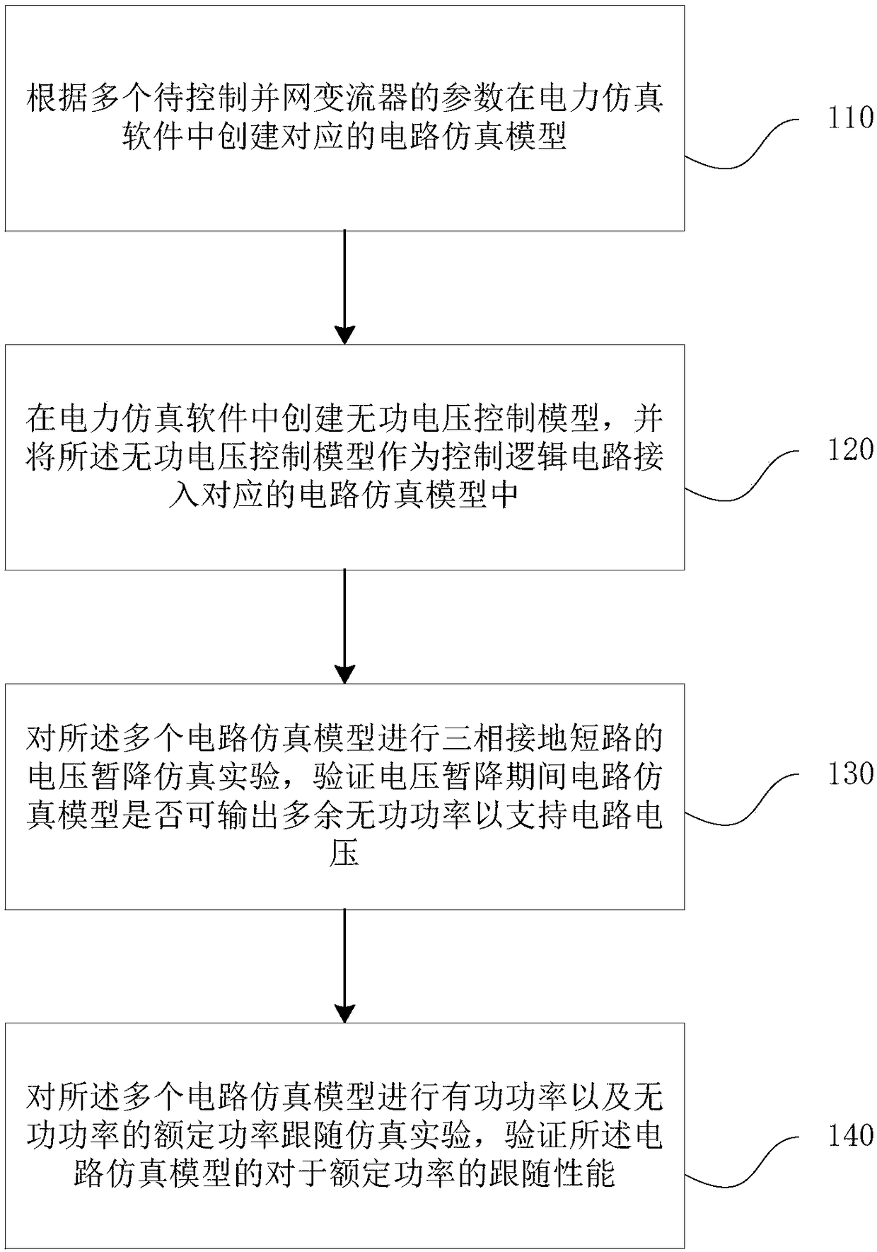
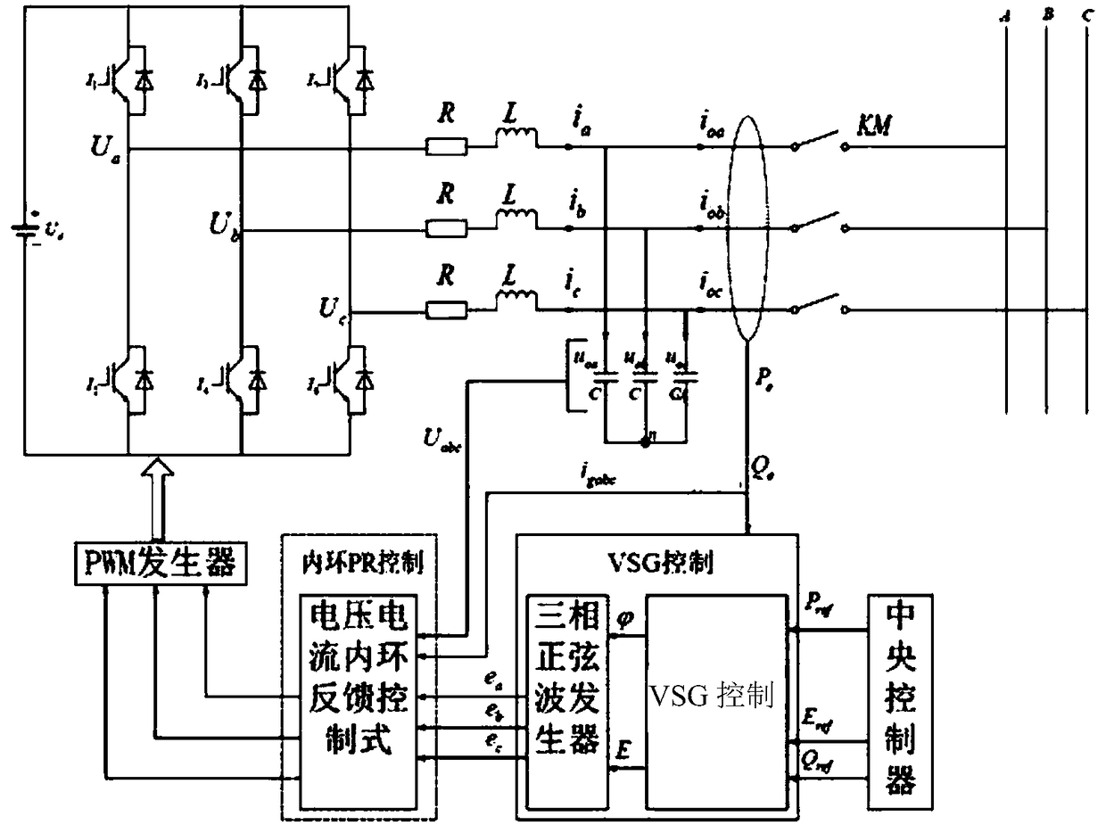
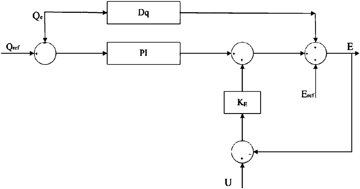
[0003] In order to solve the problems existing in the background technology that current converter usage scenarios are limited, and its control method cannot simultaneously meet the needs of different power grids for different usage scenarios, the present invention provides a distributed grid-connected converter reactive voltage Control circuit simulation method and system, the method and system establishes a circuit simulation model and a reactive voltage circuit control model, and obtains a control model that can switch control methods according to the type of grid access through simulation experiments, so as to meet the needs of different grids in different usage scenarios , the reactive voltage control circuit simulation method of a distributed grid-connected converter includes:

Method used


Image

  • Reactive voltage control circuit simulation method and system for distributed grid-connected converter
  • Reactive voltage control circuit simulation method and system for distributed grid-connected converter
  • Reactive voltage control circuit simulation method and system for distributed grid-connected converter

Examples


Embodiment Construction

[0035] Exemplary embodiments of the present invention will now be described with reference to the drawings; however, the present invention may be embodied in many different forms and are not limited to the embodiments described herein, which are provided for the purpose of exhaustively and completely disclosing the present invention. invention and fully convey the scope of the invention to those skilled in the art. The terms used in the exemplary embodiments shown in the drawings do not limit the present invention. In the figures, the same units / elements are given the same reference numerals.

[0036] Unless otherwise specified, the terms (including scientific and technical terms) used herein have the commonly understood meanings to those skilled in the art. In addition, it can be understood that terms defined by commonly used dictionaries should be understood to have consistent meanings in the context of their related fields, and should not be understood as idealized or over...


PUM


Abstract

The invention discloses a reactive voltage control circuit simulation method and system for distributed grid-connected converter. The method includes: creating a corresponding circuit simulation modelin the power simulation software according to parameters of the plurality of grid-connected converters to be controlled; creating a reactive voltage control model, and connecting the reactive voltagecontrol model as a control logic circuit to a corresponding circuit simulation model; performing a voltage sag simulation experiment on the plurality of circuit simulation models to verify whether the circuit simulation model during the voltage sag can output excess reactive power support circuit voltage; performing a follow-up simulation experiment of reactive power on the plurality of circuit simulation models to verify the following performance of the circuit simulation model for rated power. The method and system establish a circuit simulation model and a reactive voltage circuit controlmodel, and obtain a control model that can be switched according to the access grid type control method through simulation experiments to meet different grid requirements of different usage scenarios.

Description

technical field [0001] The invention relates to the field of electric power control, and more specifically, to a method and system for simulating a reactive voltage control circuit of a distributed grid-connected converter. Background technique [0002] A converter is an electrical device that changes the voltage, frequency, number of phases, and other electrical quantities or characteristics of a power system, including an inverter; an inverter uses a high-frequency bridge circuit in the power grid to convert direct current into alternating current Electronic devices are widely used in the power field; with the increasing variety of power usage scenarios, converters will be used in a variety of power grids; and the main needs of converters used in large power grids are their orientation The power transmitted by the grid is accurate, meets the power value required by the grid, and has good power following performance, and can respond to changes in grid demand in a timely man...

Claims


Application Information

Patent Timeline
IPC IPC(8): H02J3/38H02J3/16
CPCH02J3/16H02J3/38H02J2203/20Y02E40/30
Inventor 唐酿盛超陈晓科黄辉黄明欣陈迅赵兵
Owner ELECTRIC POWER RES INST OF GUANGDONG POWER GRID
Learn More