
Lights that allow wireless communication

A wireless communication and wireless technology, applied in the direction of short-distance communication services, electrical components, etc., to achieve the effect of automatic grouping

Active Publication Date: 2020-04-21
SIGNIFY HLDG BV
View PDF7 Cites 0 Cited by
  • Summary
  • Abstract
  • Description
  • Claims
  • Application Information

AI Technical Summary

Problems solved by technology

[0005] However, a project to replace all the older tubes in the office with TLEDs etc. will require a commissioning process

Method used


Image

  • Lights that allow wireless communication
  • Lights that allow wireless communication
  • Lights that allow wireless communication

Examples


Embodiment approach

[0126] An exemplary embodiment of a technique for intentionally modulating the load placed on the ballast 10 by the master device 12a in order to signal a pattern in the power supplied by the ballast 10 to luminaires 4 in the same luminaire 4 is now described below. Lamps 12a-d.

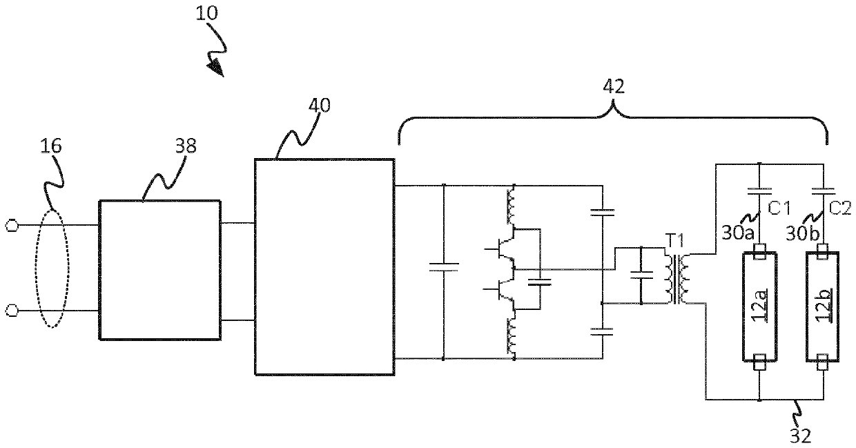
[0127] As discussed, fluorescent illuminators 4 typically employ several TL tubes 12a - d wired to a single ballast 10 . Figure 4 A typical wiring diagram for an instant-start (IS) ballast 10 is shown in . At each end of the TL tube 12, two pins 22 are shorted by a shunt lamp holder. Pin 22a,i at one end of a first lamp 12a in luminaire 4 is connected to ballast 10 via a first blue wire 30a, and pin 22b,1 at one end of second lamp 12b is connected via a second blue wire 30a. Wire 30a is connected to ballast 10 (and so on if there are more than two lamps in the luminaire). At the other end, the pins 22a, ii and 22b, ii (etc.) are all connected together and to the ballast 10 via the same red wire 3...


PUM


Abstract

Each of the plurality of components including the first light is operable in a first mode in which it appears to the debugging tool pending debugging, and in a second mode in which it is inactive to the debugging tool. It behaves like this. Each component starts the debugging process in first mode. The first light then triggers one or more second components (eg other lights) to switch to the second mode so that during debugging the second component will not appear to the debugging tool as waiting for debugging. After this, the first lamp operates in the first mode such that it appears to the debugging tool waiting for debugging (thus collectively representing the first and second lamps). The first light also represents the second part and signals the debugging tool so that the first light and the second part can be debugged as a group.

Description

technical field [0001] The present disclosure relates to arrangements of lights that allow wireless communication, such as retrofittable LED-based replacements for traditional fluorescent tubes or filament light bulbs. Background technique [0002] A luminaire (luminaire) is a device comprising at least one lamp for emitting light and any associated sockets, supports and / or housings. Luminaires can take any of a variety of forms, such as conventional ceiling or wall mounted luminaires, freestanding luminaires or wall washers, or less conventional forms such as built into surfaces or items of furniture A light source, or any other type of lighting device used to emit light into an environment. Lamp refers to the individual light emitting components within a luminaire, where each luminaire may have one or more light emitting components. The lamp may also take any of a variety of forms, such as LED-based lamps, gas discharge lamps, or filament bulbs. An increasingly popular ...

Claims


Application Information

Patent Timeline
Patent Type & Authority Patents(China)
IPC IPC(8): H05B45/30
CPCH04W4/80H05B47/19H05B47/199H05B47/1965H05B47/00
Inventor P.戴克勒L.T.罗泽恩达亚尔陶海敏
Owner SIGNIFY HLDG BV
Learn More