Ten-switch clamping type three-phase non-isolated photovoltaic inverter topology

A technology of photovoltaic inverter and topological structure, which is applied in the direction of photovoltaic power generation, conversion of AC power input to DC power output, output power conversion device, etc., can solve the problem of increasing the harmonic content of inverter output current, reducing power quality, Increase electromagnetic interference and other problems to achieve the effects of suppressing ground leakage current, ensuring personal and equipment safety, and improving common mode characteristics

Active Publication Date: 2018-08-10
NANJING UNIV OF POSTS & TELECOMM
View PDF5 Cites 2 Cited by
  • Summary
  • Abstract
  • Description
  • Claims
  • Application Information

AI Technical Summary

Problems solved by technology

The existence of leakage current will increase the harmonic content of inverter output current and increase electromagnetic interference, thereby reducing power quality, causing grid distortion, and causing unnecessary power loss, etc.

Method used


Image

  • Ten-switch clamping type three-phase non-isolated photovoltaic inverter topology
  • Ten-switch clamping type three-phase non-isolated photovoltaic inverter topology
  • Ten-switch clamping type three-phase non-isolated photovoltaic inverter topology

Examples


Embodiment 1

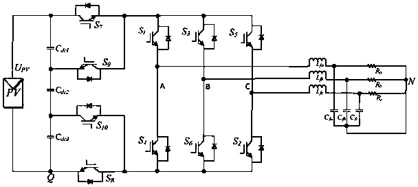
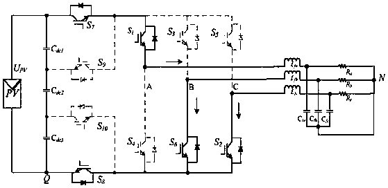
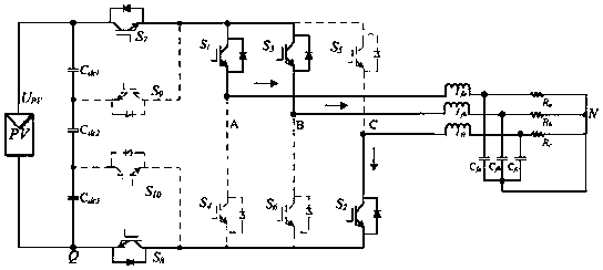
[0026] This embodiment provides a ten-switch clamp type three-phase non-isolated photovoltaic inverter topology, the structure of which is as follows figure 1 As shown, it includes three-phase six switch tubes, three-phase output filter, three-phase load and three-phase clamping circuit, and the three-phase clamping circuit includes the first input DC capacitor C dc1 , the second input DC capacitor C dc2 , The third input DC capacitor C dc3 , Upper DC switching tube S 7 , Lower DC switching tube S 8 , upper clamp switch tube S 9 and the lower clamp switch S 10 . Solar battery U pv The positive poles of the first DC capacitor C dc1 The positive pole of the upper DC switch tube S 7 The drain is connected, the upper DC switch S 7 The sources of the upper clamp switch S 9 The drain and the first switching tube S 1 , the third switch tube S 3 , the fifth switch tube S 5 connected to the drain of the solar cell U pv The negative pole of the third DC capacitor C dc3 Th...


PUM


Abstract

The invention relates to a ten-switch clamping type three-phase non-isolated photovoltaic inverter topology. The topology comprises a three-phase six-switch tube, a three-phase output filter, a three-phase load and a three-phase clamping circuit; the three-phase clamping circuit comprises a first direct current capacitor, a second direct current capacitor, a third direct current capacitor, an upper direct current switch tube, a lower direct current switch tube, an upper clamping switch tube and a lower clamping switch tube; a positive electrode of the first direct current capacitor and a drainelectrode of the upper direct current switch tube are respectively connected with a positive electrode of a solar cell; a negative electrode of the third direct current capacitor and a source electrode of the lower direct current switch tube are respectively connected with a negative electrode of the solar cell; a source electrode of the upper clamping switch tube is respectively connected with anegative electrode of the first direct current capacitor and a positive electrode of the second direct current capacitor; a drain electrode of the lower clamping switch tube is respectively connectedwith a negative electrode of the second direct current capacitor and a positive electrode of the third direct current capacitor; a source electrode of the upper direct current switch tube is connected with a source electrode of the upper clamping switch tube; and a drain electrode of the lower direct current switch tube is connected with a source electrode of the lower clamping switch tube. The ten-switch clamping type three-phase non-isolated photovoltaic inverter topology provided by the invention has the advantages that common mode leakage current and earth leakage current can be effectively inhibited.

Description

technical field [0001] The invention relates to a topological structure of a ten-switch clamp type three-phase non-isolated photovoltaic inverter, belonging to the technical field of power electronic DC-AC conversion. Background technique [0002] Photovoltaic inverters require high conversion efficiency, low cost, and can withstand the adverse effects of large output voltage fluctuations of photovoltaic cells, and their AC output must also meet high power quality. Photovoltaic inverters can be divided into isolated type and non-isolated type according to whether they have an isolation transformer. The isolated photovoltaic inverter realizes the electrical isolation of the power grid and the battery panel, and ensures the safety of people and equipment, but it is bulky, expensive, and the system conversion efficiency is low. The structure of the non-isolated photovoltaic inverter does not contain a transformer, so it has the advantages of high efficiency, low cost, and smal...

Claims


Application Information

Patent Timeline
IPC IPC(8): H02M7/487H02M1/12
CPCH02M1/12H02M7/487H02M1/123Y02E10/56
Inventor 马海啸段新锋张晓峰
Owner NANJING UNIV OF POSTS & TELECOMM
Why Eureka
Try Eureka