Anesthesia tube fixator and utilization method thereof

A pipe fixing and arc-shaped technology, which is applied in the direction of tracheal intubation, respirator, etc., can solve the problems of time-consuming and labor-intensive installation, cumbersome effects, pipe discounts, etc., and achieve the effect of convenient use, avoiding discounts, and simple installation

Inactive Publication Date: 2018-08-14
AFFILIATED YONGCHUAN HOSPITAL OF CHONGQING MEDICAL UNIV
View PDF7 Cites 1 Cited by
  • Summary
  • Abstract
  • Description
  • Claims
  • Application Information

AI Technical Summary

Problems solved by technology

[0004] The purpose of the present invention is to provide an anesthesia pipeline fixer and its use method, which are used to solve the problems of pipeline discount caused by the existing anesthesia pipeline fixation method, time-consuming and laborious installation, cumbersome effect and unsatisfactory effect

Method used


Image

  • Anesthesia tube fixator and utilization method thereof
  • Anesthesia tube fixator and utilization method thereof
  • Anesthesia tube fixator and utilization method thereof

Examples


Embodiment Construction

[0034] In order to enable those skilled in the art to better understand the present invention, the technical solution of the present invention will be further described below in conjunction with the accompanying drawings and embodiments.

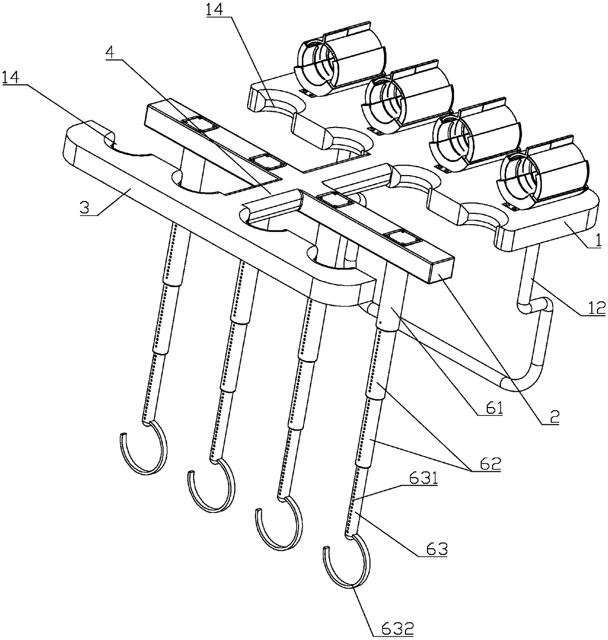
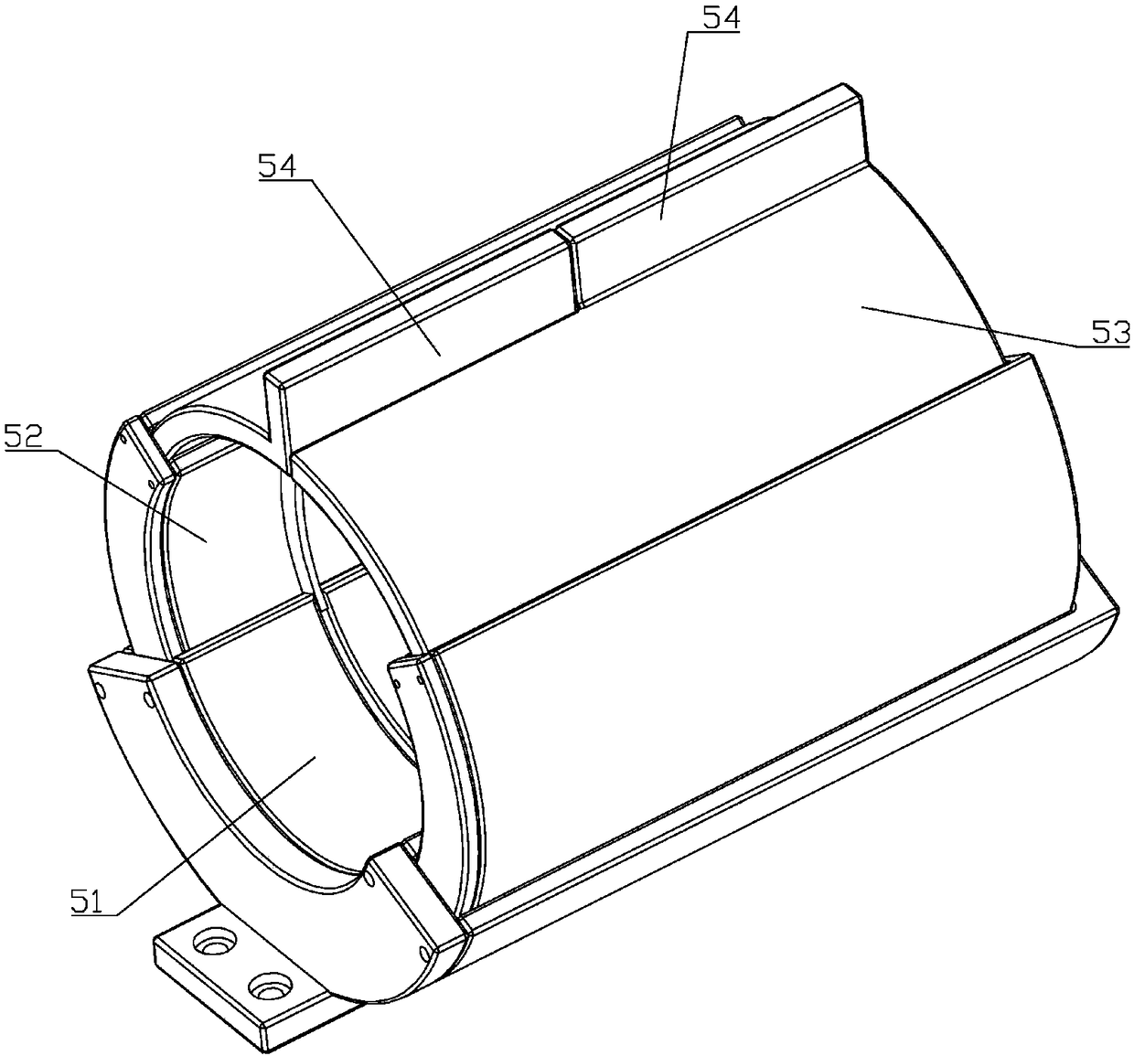
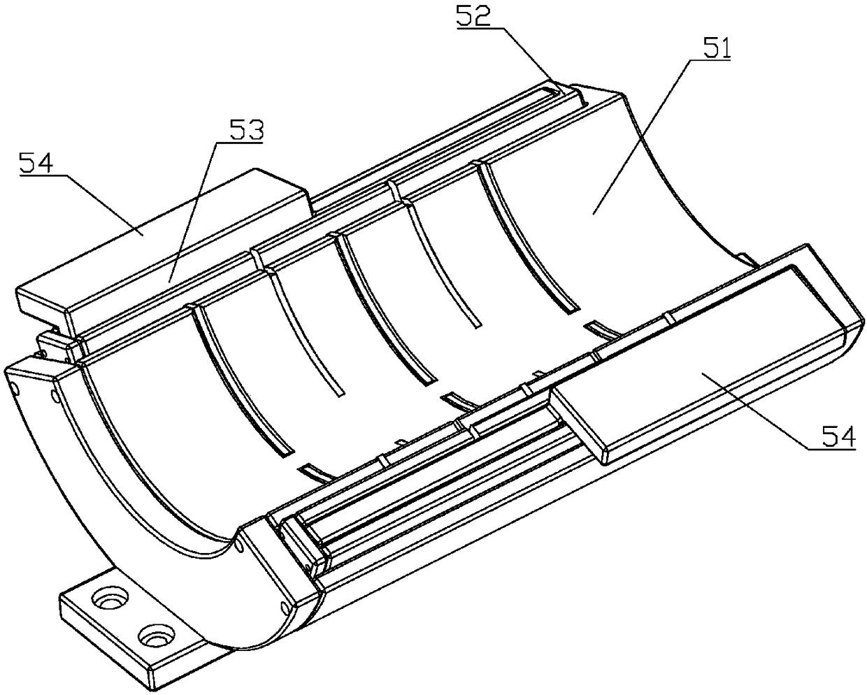
[0035] Such as Figure 1 to Figure 11 As shown, a kind of anesthesia pipeline fixer of the present invention comprises a Wang-shaped main body plate, and the Wang-shaped main body plate includes a main board 1, a middle board 2, a rear board 3 and a middle rod 4, and the front end of the lower end surface of the main board 1 is evenly provided with a plurality of inverted L-shaped hook 11, the lower end surface of the main board 1 is provided with a U-shaped support rod 12 on the outside of the inverted L-shaped hook 11, and the connection end of the U-shaped support rod 12 and the main board 1 is behind the connection end of the inverted L-shaped hook 11 and the main board 1 The lower part of the U-shaped support rod 12 is bent forward, and...


PUM


Abstract

The invention belongs to the technical field of anesthesia machine auxiliary equipment and particularly relates to an anesthesia tube fixator and a utilization method thereof. The anesthesia tube fixator comprises a body plate shaped as a Chinese character wang, and the body plate comprises a main plate, a middle plate, a rear plate and a middle rod. A plurality of inverted L shaped hooks are uniformly arranged at the front end of the lower end face of the main plate, the lower end face of the main plate is provided with a U-shaped supporting rod outside the inverted L shaped hooks, and the connection end of the U-shaped supporting rod with the main plate is behind the connection end of the inverted L shaped hooks with the main plate. The front end face of the outer wall of a second connecting cylinder is uniformly provided with a plurality of first slotted holes above second threaded holes, a third connection cylinder internally sleeves the second connection cylinder, the front end face of the outer side of the third connection cylinder is provided with a plurality of second slotted holes, second retaining blocks matched with second strip grooves in the inner wall of the second connection cylinder are arranged on left and right lateral sides of the upper end of the third connection cylinder, and hooks are arranged at the lower end of the third connection cylinder. Problems oftube bending, high time and labor consumption, complexity and unsatisfactory effects caused by an existing anesthesia tube fixing mode are solved.

Description

technical field [0001] The invention belongs to the technical field of anesthesia machine auxiliary equipment, and in particular relates to an anesthesia pipeline fixer and a using method thereof. Background technique [0002] In clinical anesthesia, the anesthesia breathing circuit is used to connect the endotracheal tube and the anesthesia machine. The anesthesia breathing circuit tube is composed of joints, three-way joints and threaded pipes. The endotracheal tube is used to insert into the patient's trachea or bronchi to maintain the patient's breathing through the anesthesia machine. However, the commonly used disposable sterile plastic endotracheal tube is soft in texture. After connecting the anesthesia breathing circuit, especially the silicone anesthesia breathing circuit Heavy, easily twisted, folded, and flattened, causing blockage or narrowing of the airway. Airway blockage can lead to death of patients due to suffocation; airway narrowing not only increases a...

Claims


Application Information

Patent Timeline
Patent Type & Authority Applications(China)
IPC IPC(8): A61M16/04
CPCA61M16/0488
Inventor 闫东
Owner AFFILIATED YONGCHUAN HOSPITAL OF CHONGQING MEDICAL UNIV
Why Eureka
Try Eureka