A high-efficiency composting device

A composting and high-efficiency technology, applied in the direction of fertilization equipment, organic fertilizers, organic fertilizer equipment, etc., can solve the problems of insufficient oxygen supply, difficult collection of beneficial fertilizers, and reduced final effect of composting, so as to avoid uneven reaction and inconvenience and cost increase, to solve the effect of rationalization

Active Publication Date: 2021-02-09
湖北鑫福农生物科技股份有限公司
View PDF5 Cites 0 Cited by
  • Summary
  • Abstract
  • Description
  • Claims
  • Application Information

AI Technical Summary

Problems solved by technology

[0008] In the existing composting device, sufficient oxygen cannot be provided, and microorganisms cannot reproduce and work better, which greatly reduces the final effect of composting; at the same time, the beneficial fertilizer after composting is not easy to collect, and manual discharge is required, which is time-consuming and expensive cost

Method used


Image

  • A high-efficiency composting device
  • A high-efficiency composting device

Examples


Embodiment 1

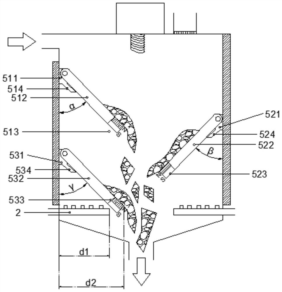
[0033]Example 1, the angle α is 55°, the angle β formed between the second baffle plate 524 and the reaction tank 1, the angle β formed between the third baffle plate 534 and the reaction tank 1 The angle γ is equal to the angle α. At this moment, the compost falling in the first 512 of the setting plate easily collides with the tail end of the second 522 of the setting plate, and the compost falling in the second 522 of the setting plate easily collides with the tail end of the third 532 of the setting plate. Collision between them will easily cause the pollution of the inner wall of the reaction tank 1 and the blockage of the air hole 21 by the impact and splash of the compost.

Embodiment 2

[0034] Example 2, the angle α is 65°, the angle β formed between the second baffle plate 524 and the reaction tank 1, the angle β formed between the third baffle plate 534 and the reaction tank 1 The angle γ is equal to the angle α. At this time, the tail of the lowermost mounting plate 3 532 collides with the air pipe 2, and d2 is smaller than d1, which may easily cause the air hole 21 to be blocked.

Embodiment 3

[0035] Example 3, the angle α is 60°, the angle β formed between the second baffle plate 524 and the reaction tank 1, the angle β formed between the third baffle plate 534 and the reaction tank 1 The angle γ is equal to the angle α. In this state, d2 is greater than d1, and there will be no collision between the falling compost between the upper and lower placement plates. At the same time, the falling compost can just fall along the axis center position of the discharge port 13 .

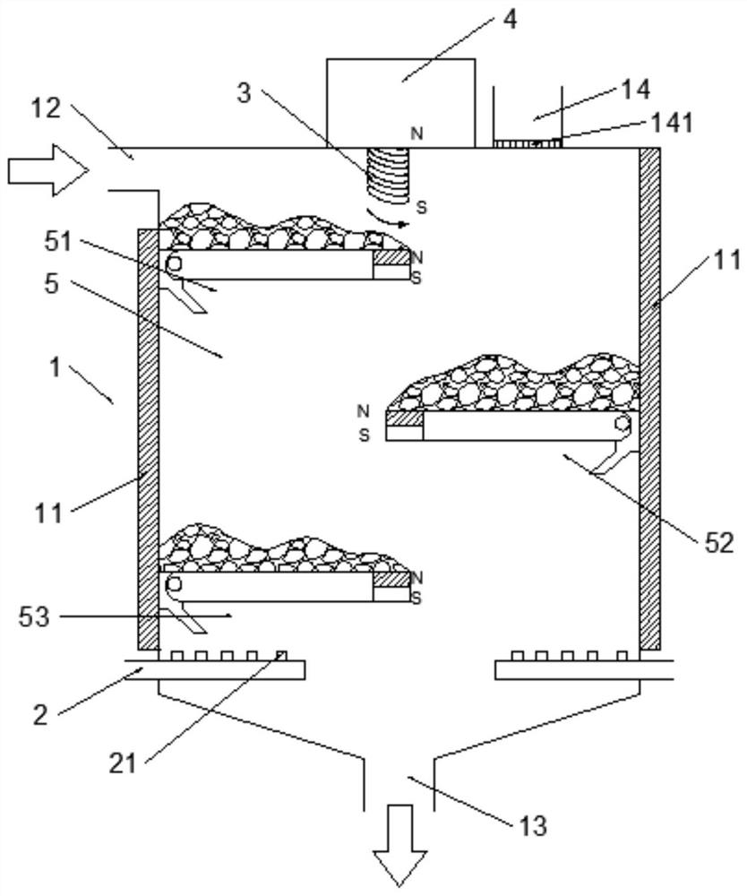
[0036] Specifically, as attached figure 1 As shown, when the energization mechanism 4 is energized, the coil 3 electrically connected to the energization mechanism 4 will also be energized, and the current trend in the coil is as follows: figure 1 As shown by the arrow in the middle curve, through Ampere's law, it is not difficult to distinguish that the top of the coil 3 is an N pole, and the bottom is an S pole. In the present invention, the magnetic pole at the top of the magnetic block 513 sho...


PUM


Abstract

A high-efficiency composting device, comprising a reaction tank, a vent pipe, a coil, an energizing mechanism, and a placement mechanism; the vent pipe is arranged horizontally below the reaction pot, and the coil is longitudinally arranged on the top of the reaction pot. The coil is electrically connected to the energizing mechanism; the placement mechanism is provided on the inner wall of the reaction tank. The beneficial effects of the present invention are: (1) the electric operation can realize the placement and discharge of compost on the placement plate through magnetic control, avoiding the inconvenience and cost increase caused by manual operation; (2) the present invention is simple in operation, simple in structure and low in cost , which not only solves the rationalized treatment of agricultural waste and waste, but also the treatment method is also environmentally friendly and energy-saving; (3) The final beneficial effect of composting is obvious and easy to control, and the oxygen supply is sufficient and uniform to avoid the phenomenon of uneven reaction.

Description

technical field [0001] The invention belongs to the field of energy saving and environmental protection, and in particular relates to a high-efficiency composting device. Background technique [0002] Energy conservation and environmental protection are part of the strategic emerging industries, which advocate energy conservation and environmental protection to save existing energy consumption, promote the development of environmentally friendly new energy, and benefit the society. First of all, we need to understand where is the energy consumption in our daily life? Where is the pollution? For the main problems, the efficiency of energy saving and environmental protection should be improved, and unnecessary energy waste should be reduced. [0003] Strategic emerging industries are based on major technological breakthroughs and major development needs, and have a major leading role in the overall economic and social development and long-term development. Industries that ar...

Claims


Application Information

Patent Timeline
Patent Type & Authority Patents(China)
IPC IPC(8): C05F17/90C05F17/979C05F17/60
CPCC05F17/95Y02W30/40
Inventor 彭小宝
Owner 湖北鑫福农生物科技股份有限公司
Why Eureka
Try Eureka