
A steel wire stay

A rope fixation and steel wire rope technology, which is applied in the direction of transmission elements or pulley ropes or cables, belts/chains/gears, mechanical equipment, etc., can solve the problem that there is no elastic component in the steel wire rope fixing seat

Active Publication Date: 2019-07-26
VITAL INT ELEVATORING EQUIP
View PDF4 Cites 0 Cited by
  • Summary
  • Abstract
  • Description
  • Claims
  • Application Information

AI Technical Summary

Problems solved by technology

In certain circumstances, one end of the steel wire rope needs to be fixed for use. The traditional steel wire rope fixing seat does not have an elastic component. In certain circumstances, it is necessary to give the steel wire rope a certain pulling margin so that the steel wire rope can still be pulled after being straightened. A small amount of distance, the traditional steel wire rope fixing seat does not have this function

Method used


Image

  • A steel wire stay
  • A steel wire stay
  • A steel wire stay

Examples


specific Embodiment approach 1

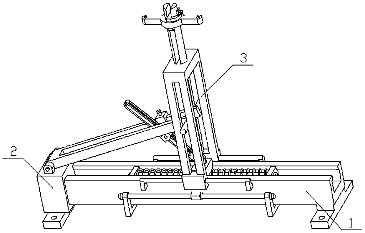
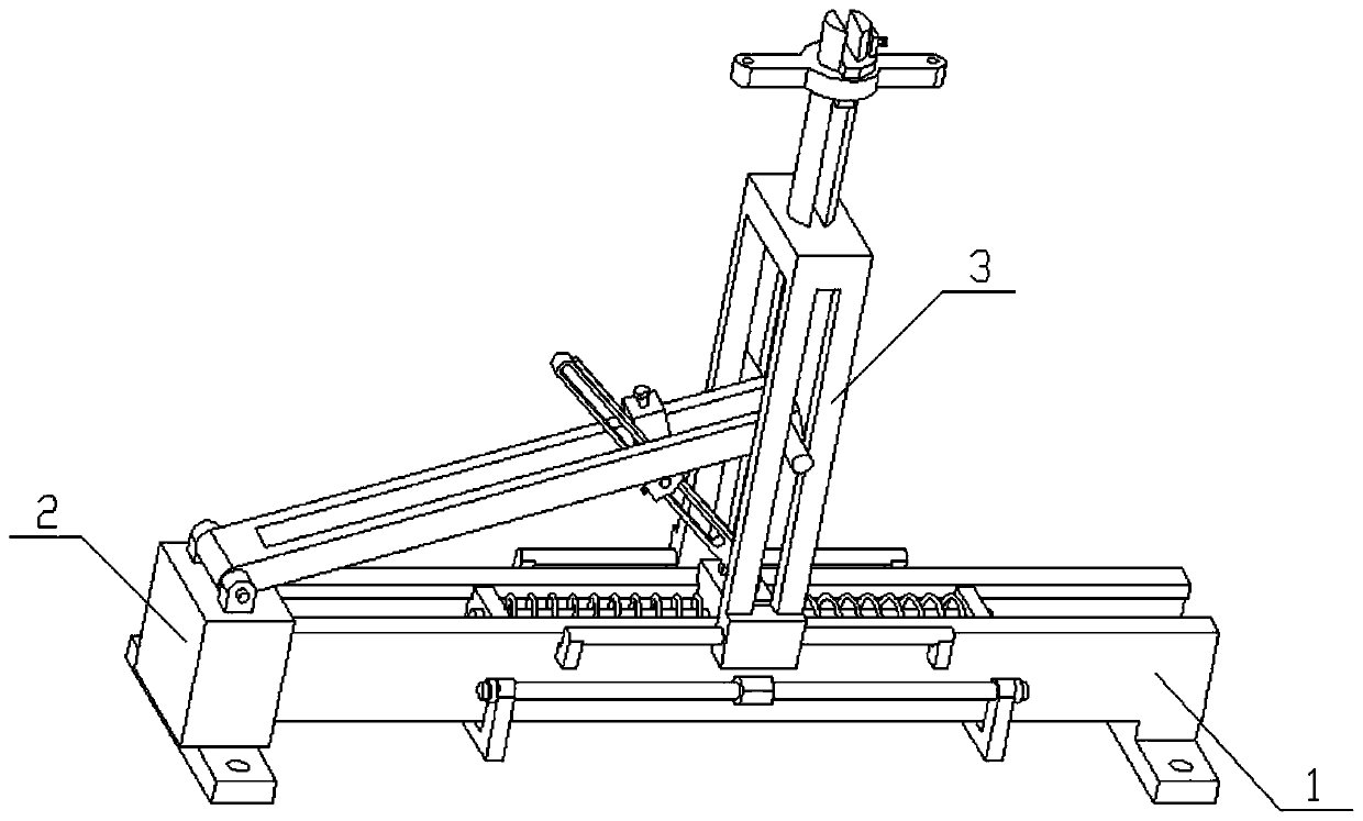
[0026] Combine below Figure 1-10 To illustrate this embodiment, the present invention relates to a fixed seat, more specifically, a steel wire stay rope fixed seat, which includes an elastic seat body 1, a force transmission component 2 and a wire rope connector 3, and one end of the steel wire stay rope can be tied to the On the device, and the left and right ends of the device can be tied into the steel wire rope, and the steel wire rope can still be pulled a small distance after straightening, which is convenient to adapt to the specific situation of the steel wire rope in actual use; and the tension of the steel wire rope is fixed. , when the pulling force is transmitted to the spring, the magnitude of the spring force can be adjusted as required, thereby controlling the magnitude of the elastic force given by the device to the steel wire stay rope.

[0027] The elastic seat body 1 includes a seat post 1-1, a seat post inner groove 1-2, a rib 1-3, a middle slider 1-4, a s...


PUM


Abstract

The invention relates to a fixing base, in particular to a steel wire pull rope fixing base. One end of a steel wire pull rope can be tightened on a device; the left and right ends of the device can be tightened into the steel wire rope; and the steel wire pull rope can be pulled by a slight distance after straightening for specific conditions of the steel wire pull rope in actual use. A base rodinner groove is formed in a base rod; convex edges are arranged on the front and back inner sides of the upper end of the base rod; a middle slide block is slidingly connected between the two convex edges; the left and right ends of the middle slide block are fixedly connected with spring sleeve rods; two spring stoppers are symmetrically arranged at the left and right ends in the base rod inner groove; the outer ends of the two spring sleeve rods are slidingly connected to the two spring stoppers; springs sleeve the two spring sleeve rods; the springs are positioned between the middle slide block and the spring stoppers; two round rail rods are provided; round rail rod edge bases are fixedly connected to the left and right ends of the round rail rods; and the two round rail rods are fixedly connected to the front and back ends of the base rod through the round rail rod edge bases.

Description

technical field [0001] The invention relates to a fixed seat, more specifically to a steel wire stay rope fixed seat. Background technique [0002] The steel wire rope is a spiral steel wire bundle twisted together with steel wires whose mechanical properties and geometric dimensions meet the requirements according to certain rules. The steel wire rope is composed of steel wire, rope core and lubricating grease. The steel wire rope is first twisted into strands by multi-layer steel wires, and then twisted into a helical rope by a certain number of strands with the rope core as the center. In material handling machinery, it is used for lifting, pulling, tensioning and carrying. The steel wire rope has high strength, light weight, stable operation, and is not easy to break suddenly, and the operation is reliable. In certain circumstances, one end of the steel wire rope needs to be fixed for use. The traditional steel wire rope fixing seat does not have an elastic component. ...

Claims


Application Information

Patent Timeline
Patent Type & Authority Patents(China)
IPC IPC(8): F16G11/12
CPCF16G11/12
Inventor 孙坚博
Owner VITAL INT ELEVATORING EQUIP
Learn More